
URDF Studio product guide
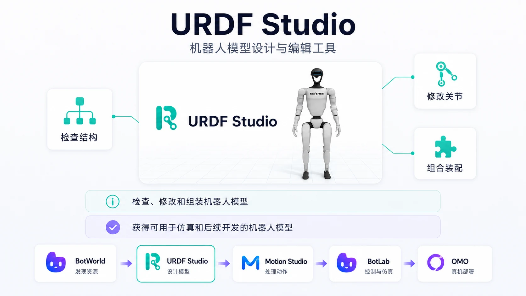
URDF Studio is the platform workbench for robot model design and assembly. Editing URDF XML by hand is error-prone and slow; URDF Studio turns robot description files into a visual workspace where you can inspect models, adjust structure, optimize collision bodies, edit physical parameters and export model files.
Typical users include robotics algorithm engineers, ROS developers, hardware integration engineers and simulation engineers.
Note: The current version does not support online saving. If you refresh or close the page, unsaved changes will be lost. After each important editing stage, export the model file or project file locally.
Save staged versions such as g1_original, g1_joint_checked_v1, g1_collision_optimized_v2 and g1_final.
URDF uses standard SI units: length in meters (m), angle in radians (rad) and mass in kilograms (kg). If the model data comes from CAD software that uses millimeters, check the scale after import.
Workspace Overview
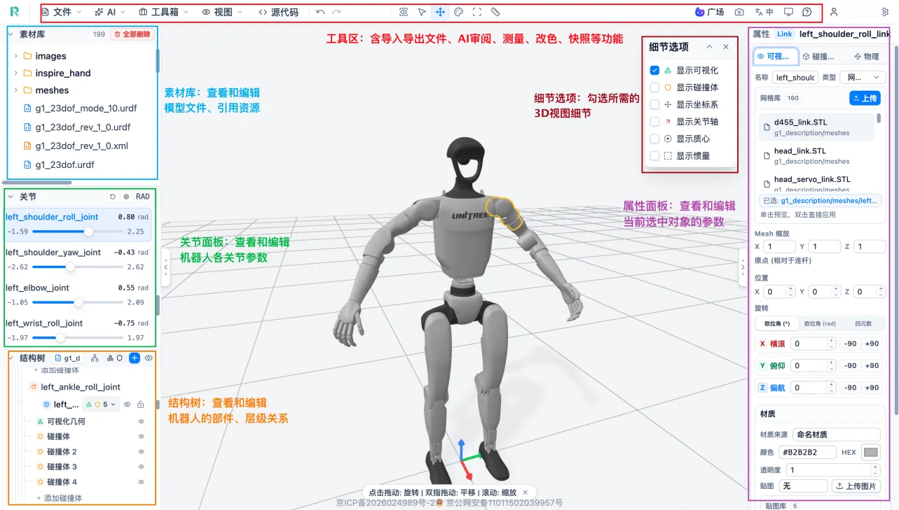
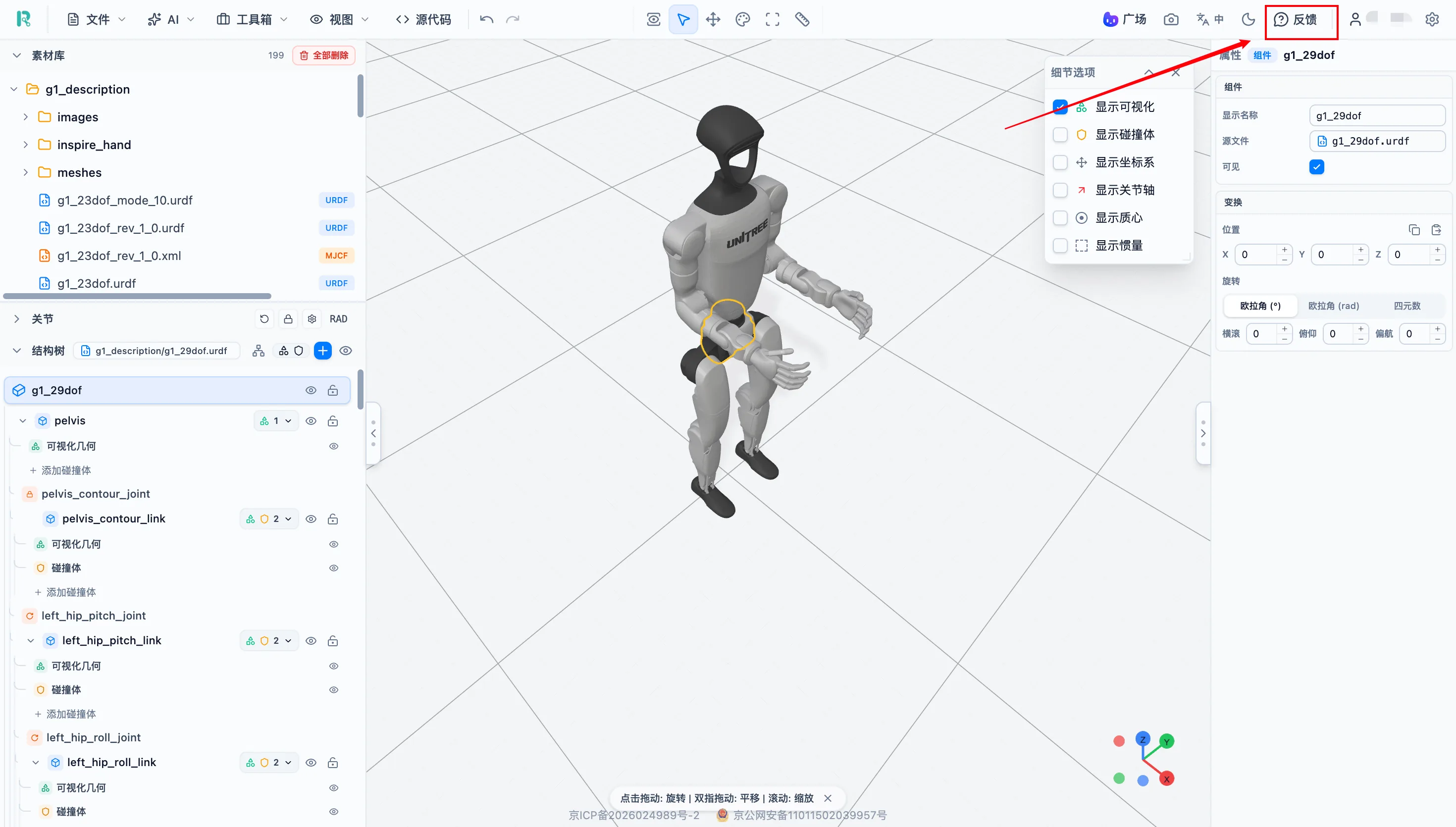
The complete URDF Studio workspace includes the top toolbar, asset library, joint panel, structure tree, detail options, 3D view and properties panel.
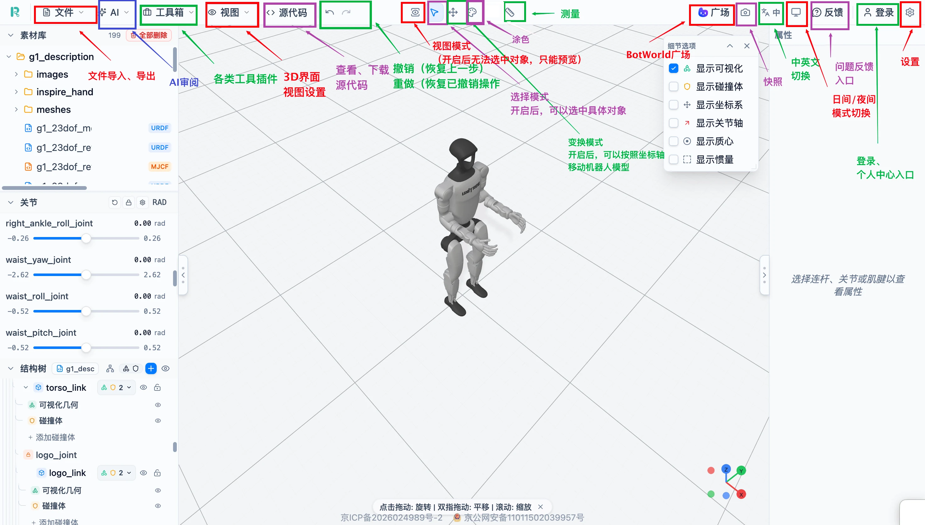
The top toolbar contains common commands such as file import, measurement, AI review, source code, undo/redo, snapshot and export.
| No. | Area | Location | Function |
|---|---|---|---|
| 1 | Top toolbar | Top of the page | File import, measurement, AI review, source code, undo/redo, snapshot and export |
| 2 | Asset library | Upper left | Manage model files, meshes, textures and referenced resources |
| 3 | Joint panel | Left side | View joint names and motion ranges; drag sliders to preview joint motion |
| 4 | Structure tree | Left side | Show the hierarchy of links, joints, visual geometry and collision bodies |
| 5 | Detail options | Upper-right of the 3D view | Toggle visual model, collision body, coordinate frame, joint axis, center of mass and inertia display |
| 6 | 3D view | Center of the page | View, select and manipulate the robot model; preview edit results in real time |
| 7 | Properties panel | Right side | View and edit pose, geometry, material, joint and physical parameters for the selected object |
For a first pass through a model, use this order: check the asset library -> confirm the 3D model -> understand the hierarchy in the structure tree -> test with the joint panel -> check geometry and collision bodies -> check physical parameters -> export a backup.
Model Import and Integrity Checks
After importing a model, complete integrity checks before editing parameters.
| Method | Description | Use case |
|---|---|---|
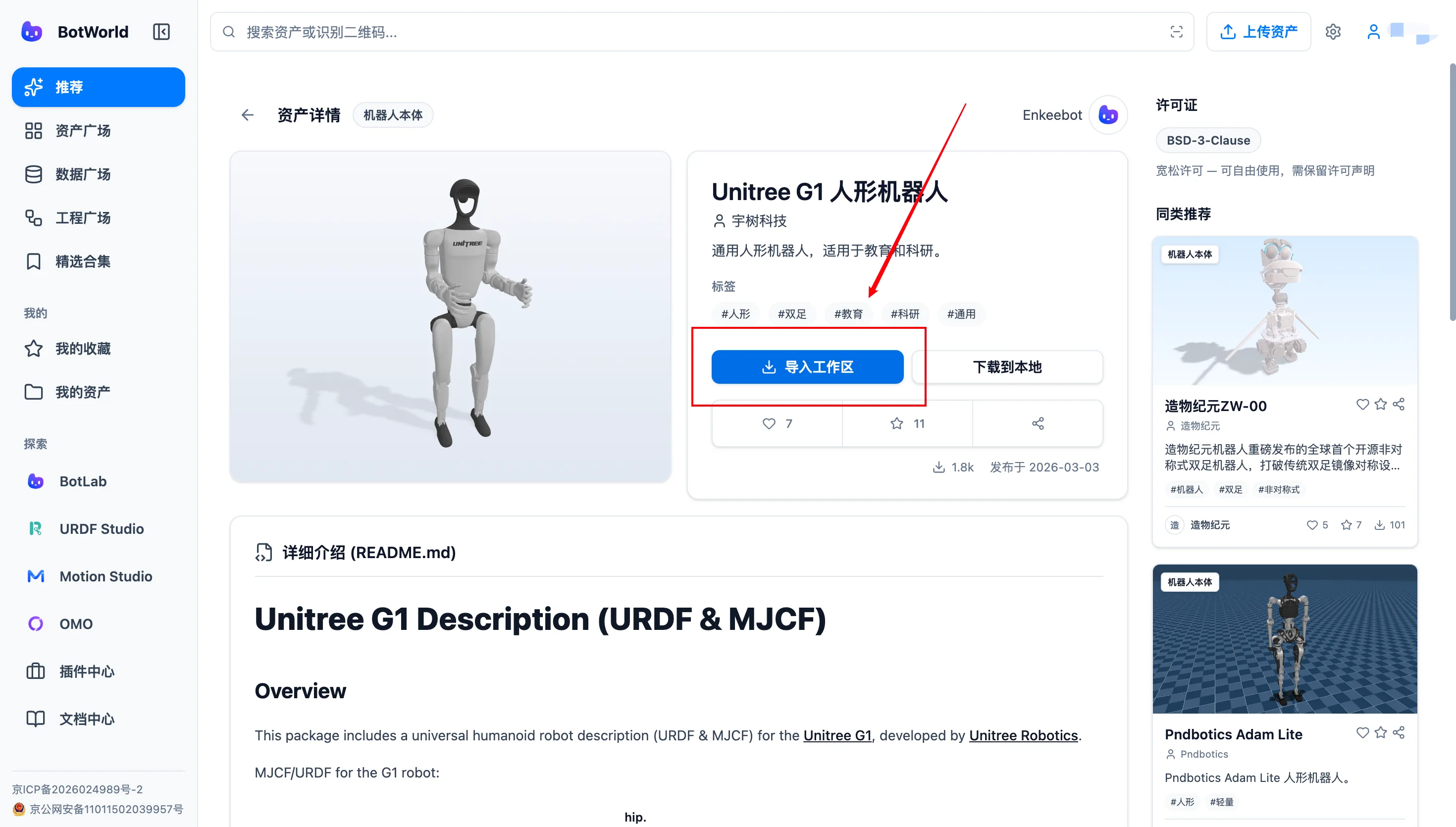
| Import from BotWorld | Click "Import to workspace" on the resource detail page | Online platform workflow |
| Local import | Select a single file, complete folder or ZIP package | Local model resources |
Import From BotWorld
On a BotWorld resource detail page, click "Import to workspace". The page opens URDF Studio and starts loading the model.
Do not delete files that are still referenced by the model; otherwise parts or textures may be missing.
Local Import
Path: top "File" menu -> choose an import method -> select a local file -> wait for loading to complete.
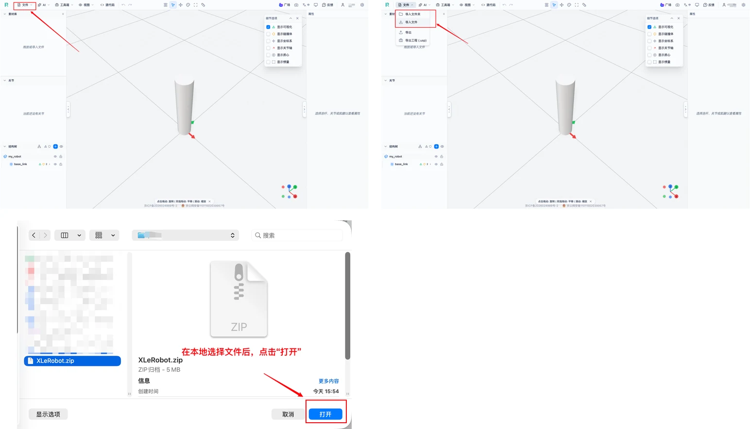
If the model contains meshes, textures or other related resources, import the complete folder or ZIP package. ZIP packages should preserve the original directory structure; do not copy only the description file and omit meshes.
Three-Way Check: Asset Library, Structure Tree and 3D View
After import, confirm the model loaded correctly from the asset library, structure tree and 3D view.
| Check area | Operation | What to watch |
|---|---|---|
| Asset library | Expand folders and confirm meshes and images exist | Complete files and correct reference paths |
| Structure tree | Expand the robot model | All links and joints appear correctly |
| 3D view | Inspect from front, side, back, top and bottom | Missing parts, texture errors or scale distortion |
Loading progress is shown during import. Wait until it finishes.
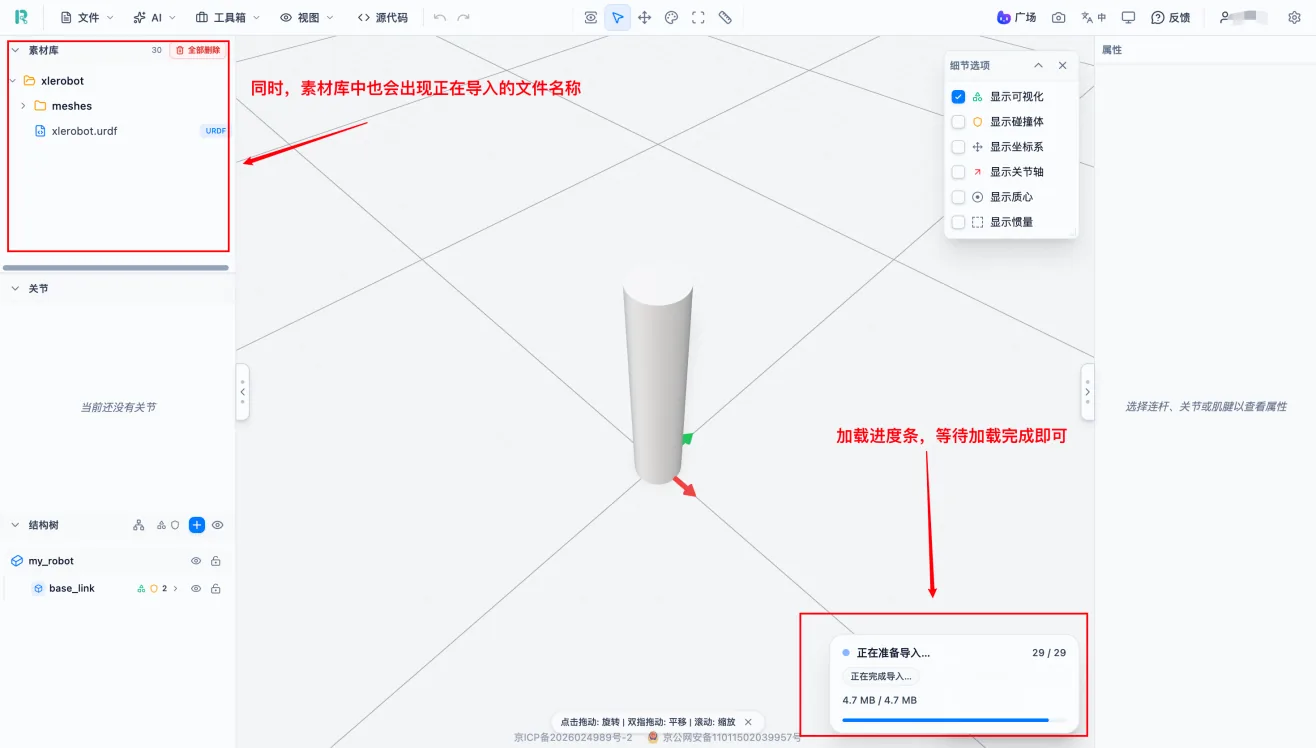
After import completes, check whether the complete robot appears in the 3D view.
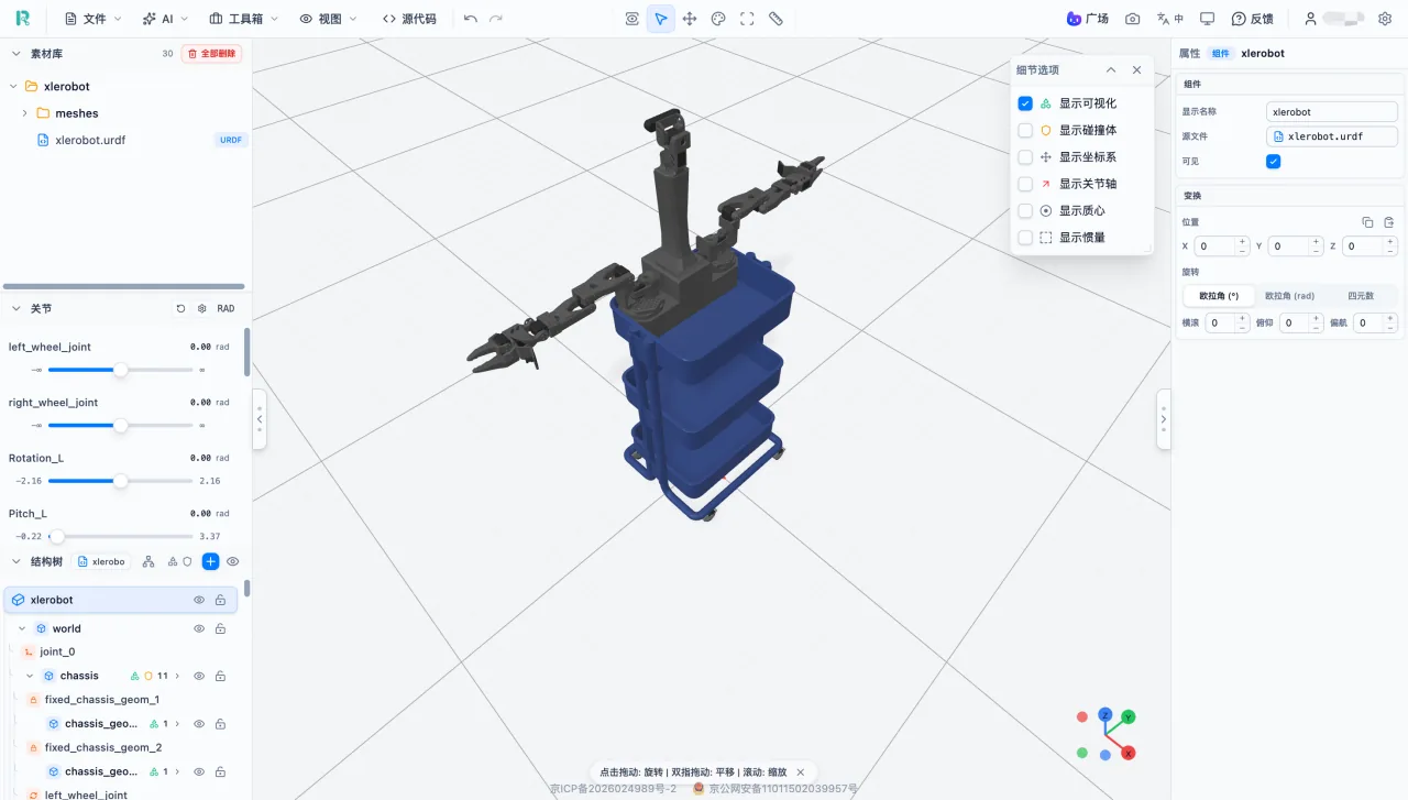
If you find a problem, check files and reference paths before changing structure.
If you imported multiple files at once, find the target resource in the asset library and click "Add".
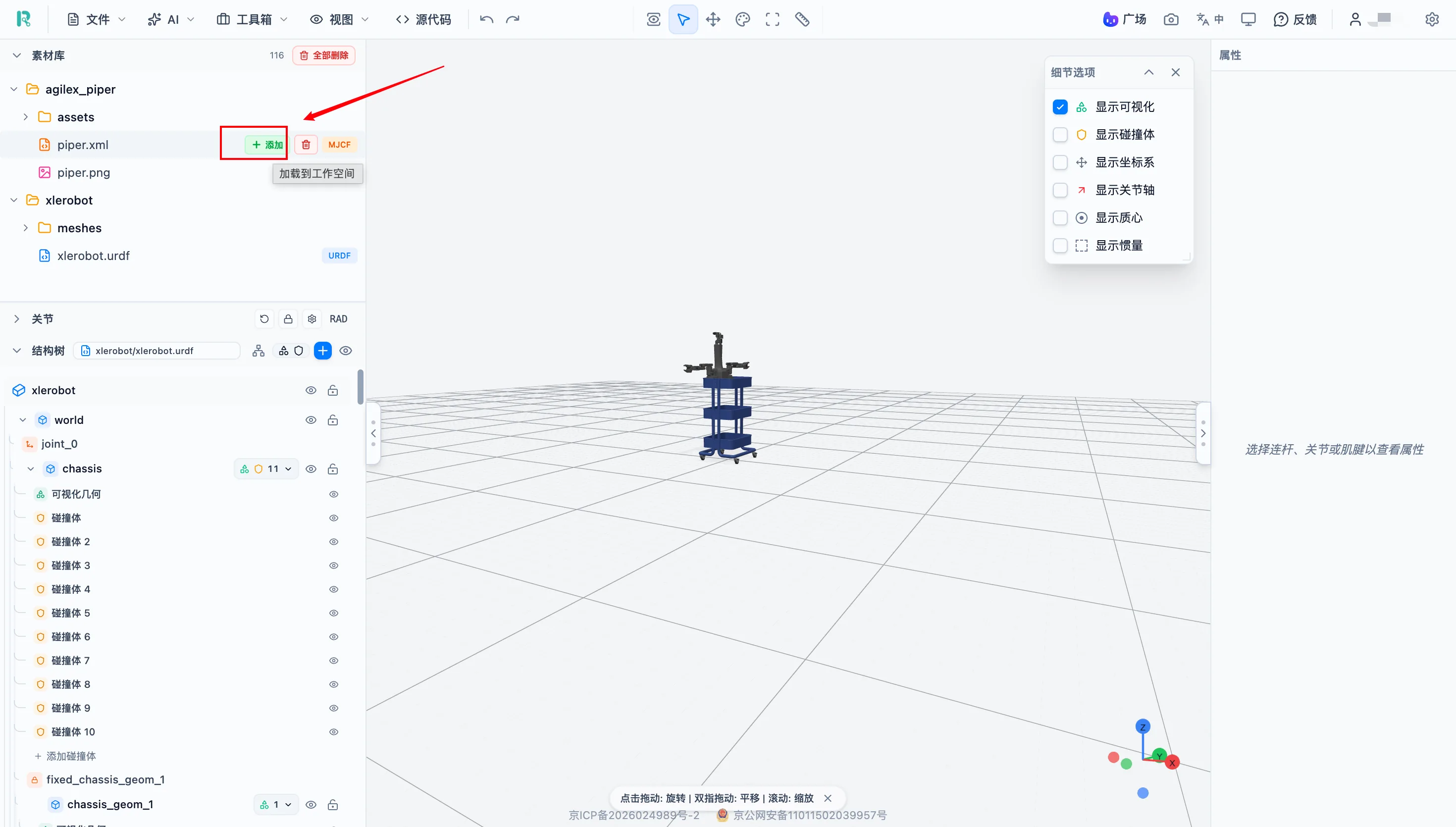
After adding the asset, it appears in the 3D view.
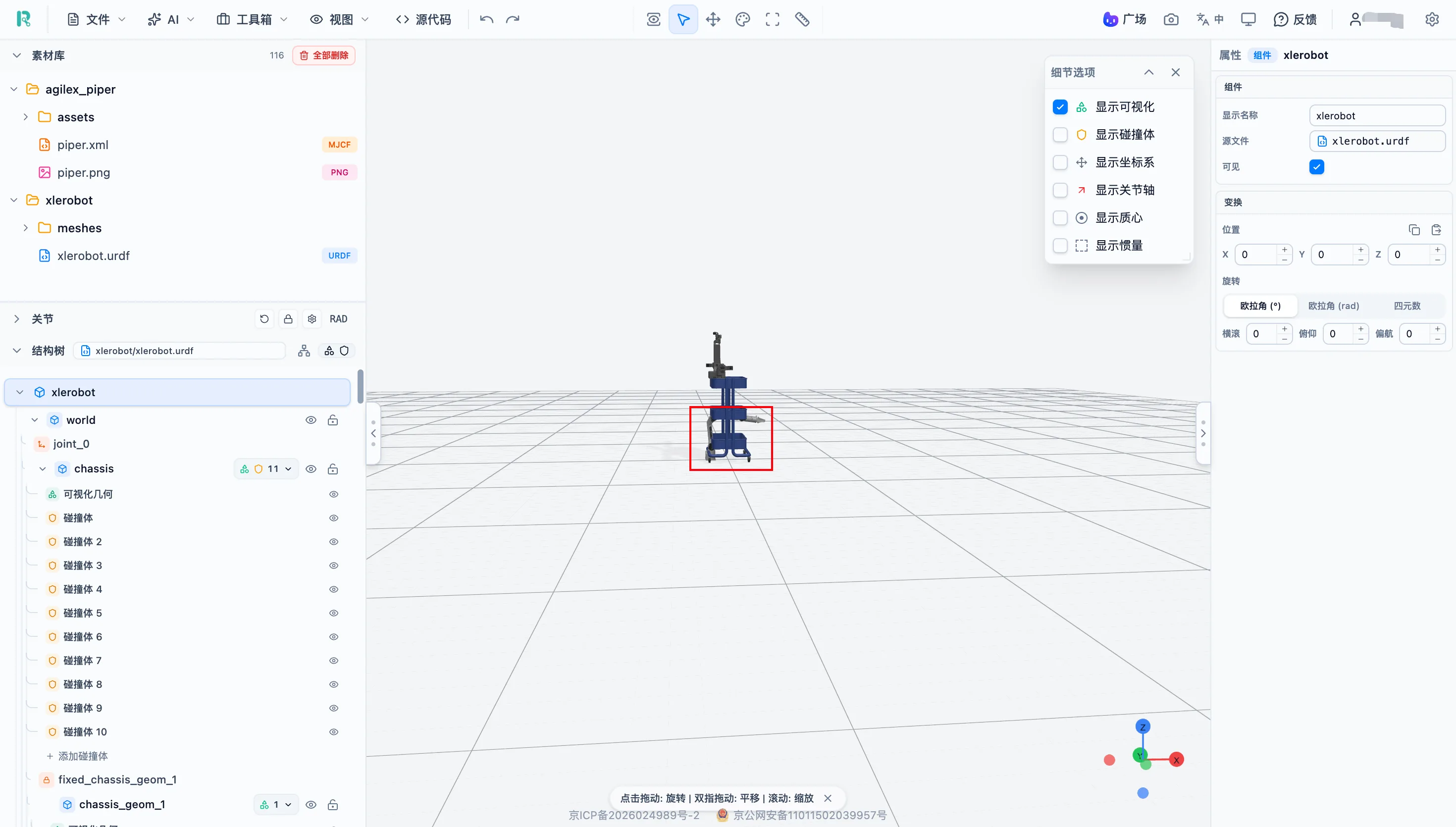
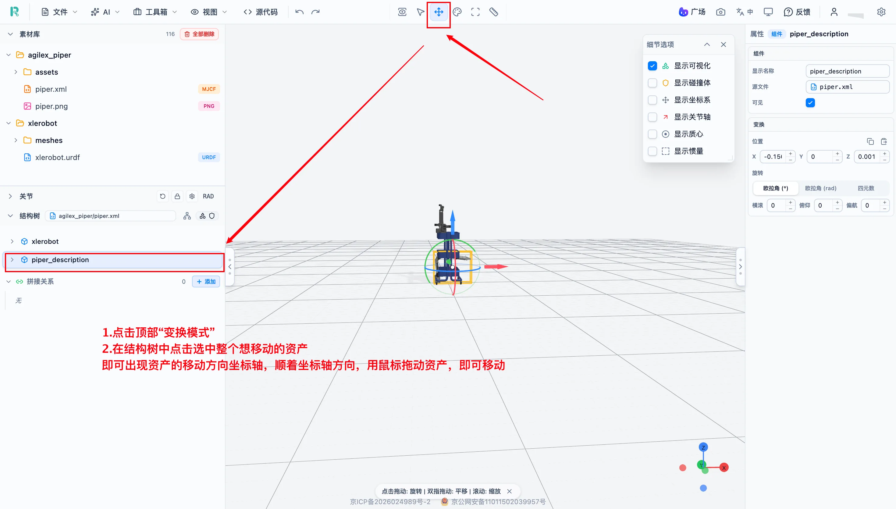
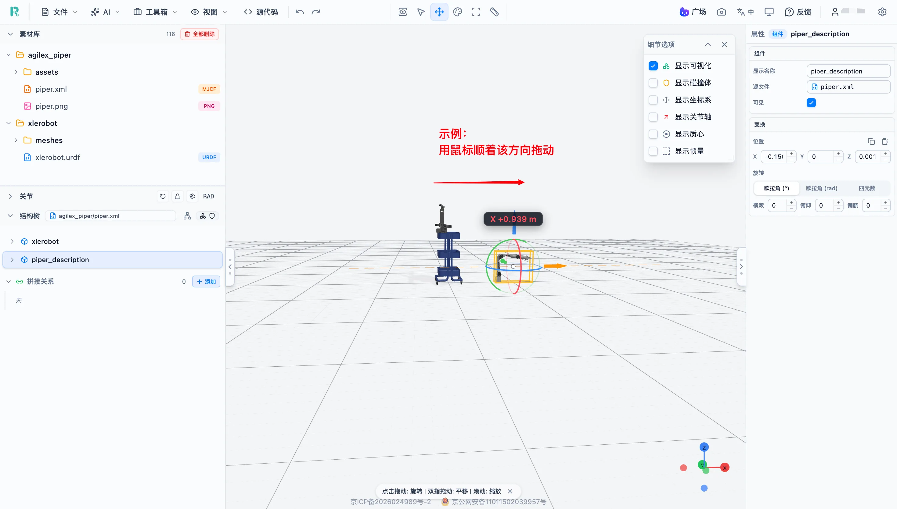
If multiple assets overlap, use Transform Mode to move or rotate objects.
Understand Robot Structure
Link and Joint
| Object | Meaning | Example |
|---|---|---|
| Link | A rigid robot part | Torso, upper arm, lower leg |
| Joint | A connection between two links | Shoulder joint, knee joint |
| Visual geometry | The robot appearance | Detailed mesh model |
| Collision body | Geometry used for physics collision | Simplified primitive shape |
Joint Type Quick Reference
URDF commonly defines four joint types. Choosing the wrong joint type directly affects simulation behavior, so choose based on the real motion.
| Joint type | Motion | Range | DOF | Typical use |
|---|---|---|---|---|
| Fixed | No motion | None | 0 | Fixed camera, base mount |
| Revolute | Rotates around an axis | Limited, such as 0 deg to 180 deg | 1 | Arm elbow, wrist |
| Continuous | Rotates around an axis | Unlimited rotation | 1 | Wheel, turntable |
| Prismatic | Moves along an axis | Limited travel | 1 | Telescopic arm, linear rail |
In short, fixed joints are locked; revolute and continuous joints both rotate, but only revolute joints have range limits; prismatic joints slide along an axis.
Structure Tree Hierarchy
Typical hierarchy: root -> Link (Visual + Collision) -> Joint -> Link (Visual + Collision) -> ...
Click an object name in the structure tree to highlight the corresponding object in the 3D view. Editing or deleting an upper-level object affects all child parts, so export a project backup before structural changes.
Visual Geometry vs Collision Body
| Item | Visual geometry | Collision body |
|---|---|---|
| Purpose | Displays appearance | Collision calculation |
| Complexity | Usually detailed mesh | Usually simplified primitive geometry |
| Effect on simulation | Does not affect physics calculation | Directly affects collision detection and simulation stability |
| Effect of changing color | Changes robot appearance | Does not change robot appearance |
Use Detail Options to display them separately and compare their positions and sizes.
Check and Modify Joints
Models from other sources may have unreasonable joint ranges, incorrect installation directions, or joint axes that do not match the real mechanism. Check key joints one by one after import to avoid abnormal simulation behavior.
Joint Panel Preview
The joint panel shows joint name, current angle, minimum and maximum motion range, and a slider.
Operation: find the target joint in the joint panel -> drag the slider -> observe the corresponding part in the 3D view -> move to minimum and maximum positions to check direction and part interference.
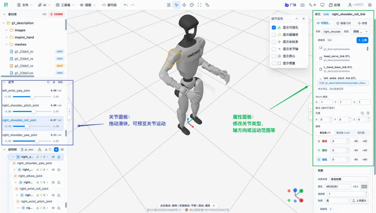
Note: The joint panel is for preview. Formal edits to joint type, axis direction or range should be made in the properties panel.
Modify Joint Parameters
Operation: select a Joint in the structure tree -> view the right properties panel -> check or modify:
- Parent Link and child Link.
- Joint type.
- Joint origin position and rotation.
- Joint axis direction.
- Minimum and maximum values.
After editing, return to the joint panel and preview the full motion range again.
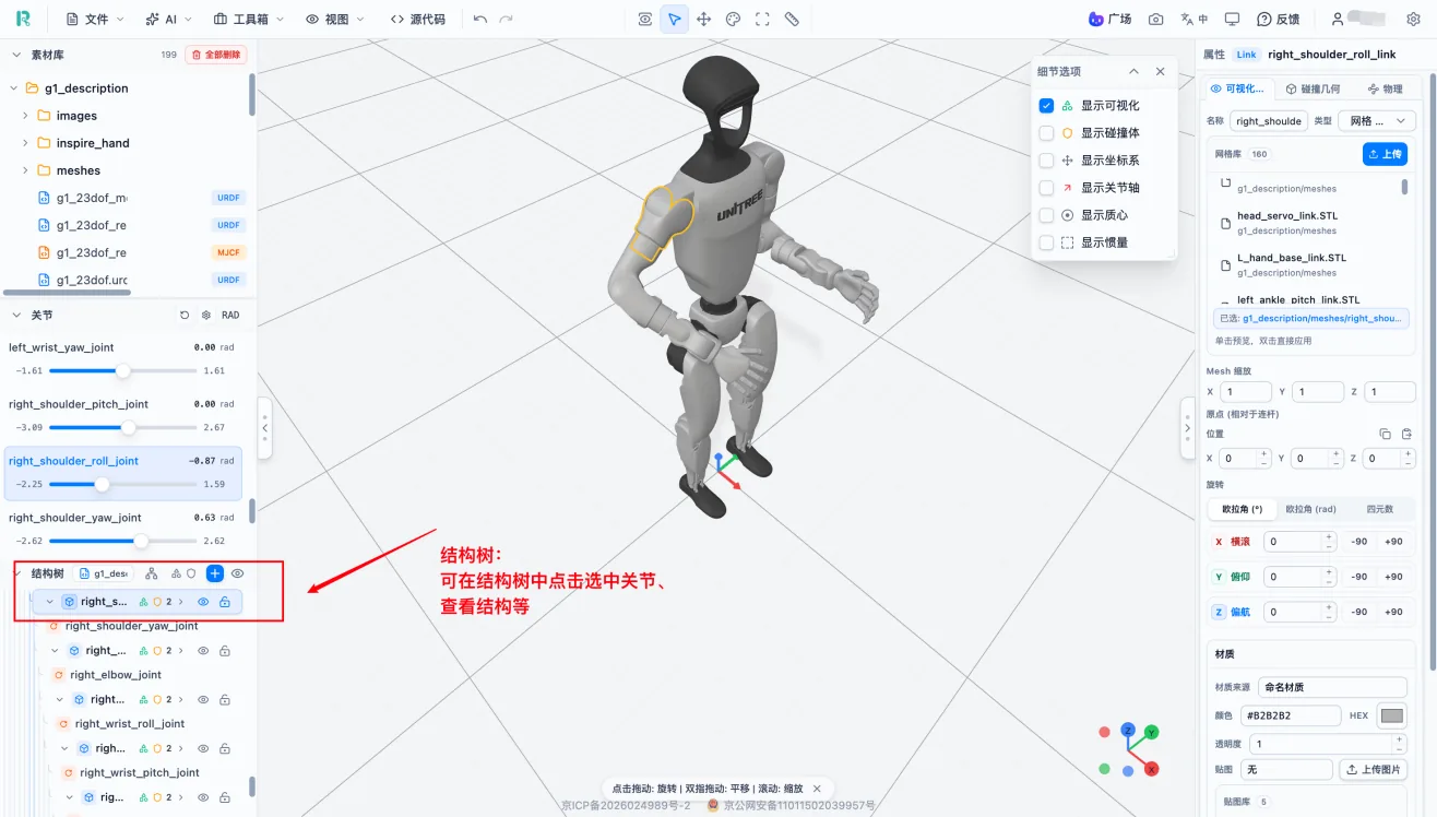
Note: After changing joint axis or origin, test the full motion process. Do not check only the initial pose.
Coordinate Frames and Joint Axis Display
Operation: open Detail Options -> enable "Show coordinate frame" and "Show joint axis" -> drag the slider to check whether actual motion matches the joint axis.
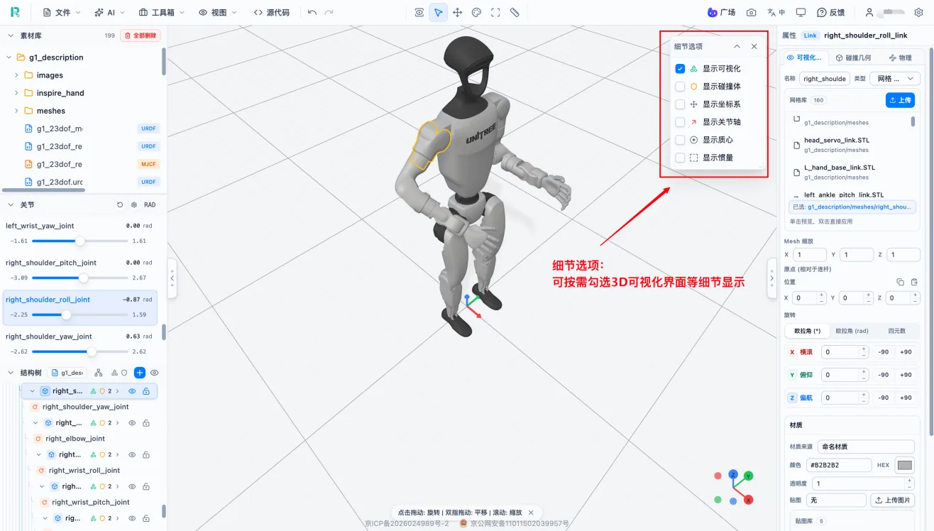
Use this when troubleshooting wrong joint motion direction, checking component installation direction, or comparing symmetric joints on both sides of a robot.
Modify Robot Appearance
Adjust Part Pose
Operation: select the target object -> edit Position X/Y/Z and Rotation parameters in the properties panel -> inspect from multiple views -> preview related joint motion.
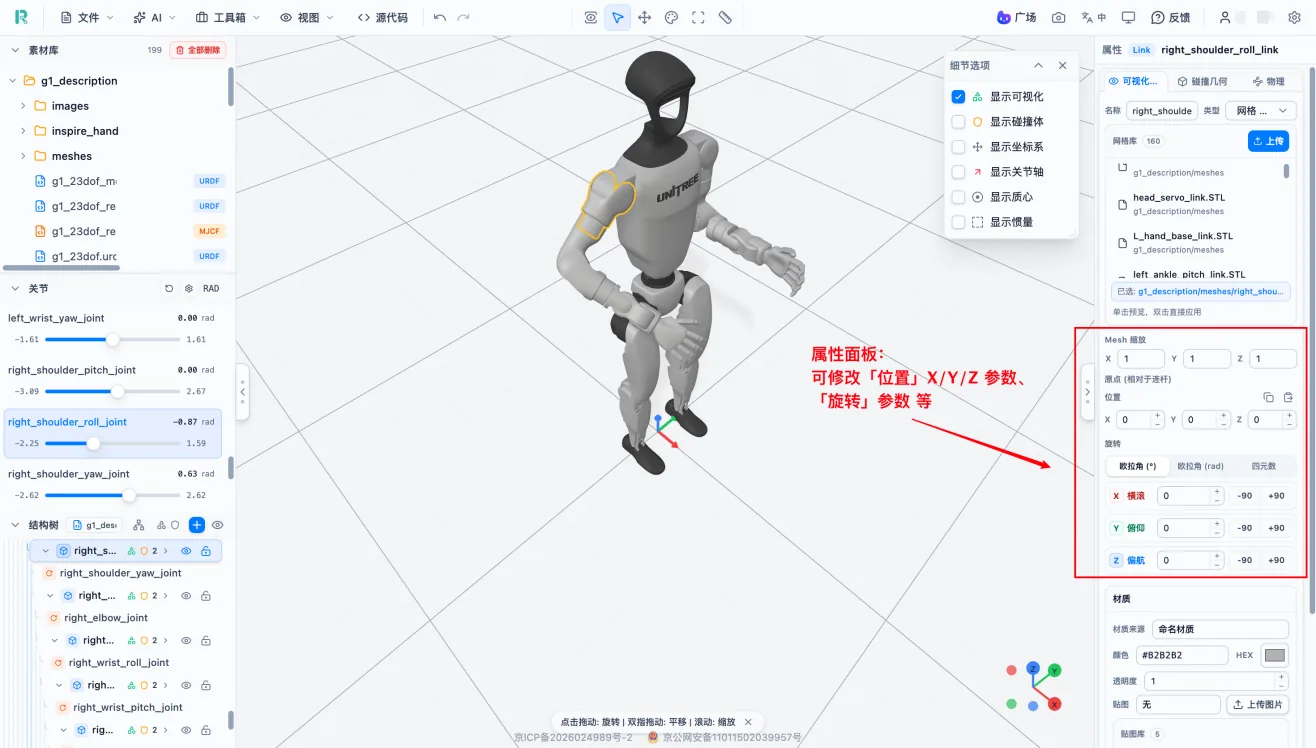
Recommendations:
- Record original values before editing.
- Adjust only one direction at a time.
- Link, visual geometry and collision body poses are independent.
- After editing a visual model, check the collision body as well.
Edit Visual Geometry
Operation: expand a Link in the structure tree -> select visual geometry -> open the "Visual" tab in the properties panel -> inspect mesh file references -> adjust scale, position and rotation as needed -> return to the 3D view to confirm the result.
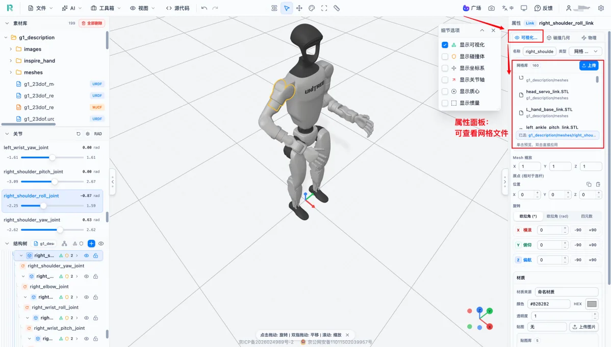
The image shows the properties panel for a visual geometry object, especially mesh file references, scale parameters and pose parameters. Mesh scale should usually stay consistent across X, Y and Z; changing only one direction may distort proportions.
Modify Color and Material
Change colors when you need to distinguish parts, mark a specific Link during debugging, create presentation images or prepare a resource cover.
Operation: select the specific visual geometry, not the Link -> open Visual properties -> modify the color or color value -> lower opacity if you want the part to appear semi-transparent for inspecting internal structure.
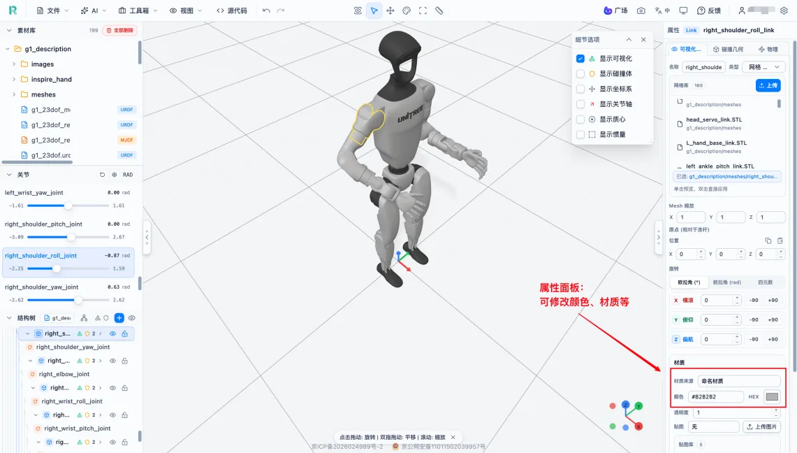
Color affects only model display. It does not change structure, collision bodies or physical parameters. If the model uses texture images, textures may override color settings.
Optimize Collision Bodies
Collision body complexity directly affects the computation cost of each simulation step. High-detail mesh collision bodies may reduce frame rate or make simulation unstable, so they are often replaced with simplified primitives such as boxes, spheres and cylinders. Collision bodies that are too simple reduce collision accuracy. The goal is to balance computation efficiency and accuracy.
View Collision Bodies
Operation: open Detail Options -> enable "Show collision body" -> optionally disable "Show visual" to view collision bodies alone -> inspect their positions and sizes from front, side and top views.
Select and Modify
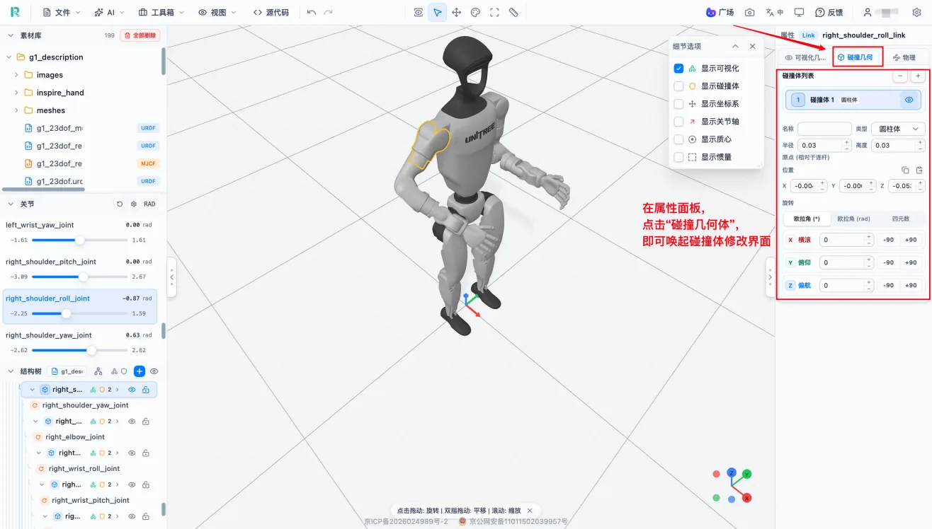
Operation: expand a Link in the structure tree -> select a collision body -> inspect geometry, position and rotation parameters in the properties panel -> adjust size, position or direction as needed.
Optimization Tools
| Tool | Description | Use case |
|---|---|---|
| Primitive fitting | Replace complex collision bodies with boxes, spheres or cylinders | Collision body uses high-detail mesh and is expensive to simulate |
| Collision simplification | Reduce collision body complexity and count | One part contains too many collision bodies |
| Coaxial merge | Merge multiple collision bodies aligned on the same axis under one Link | Multiple collision bodies can be represented more simply |
After optimization, check:
| Check item | Meaning |
|---|---|
| Coverage | Whether collision bodies cover the main visual model |
| Overreach | Whether collision bodies extend far outside the robot shape |
| Overlap | Whether adjacent parts have large collision overlaps |
| Motion check | Whether joint motion causes abnormal collisions |
Check Physical and Hardware Parameters
Mass, center of mass and inertia directly determine robot behavior in physics simulation. Invalid inertia, such as zero, negative values or wrong orders of magnitude, may produce non-physical motion such as shaking, falling or flying apart.
Mass, Center of Mass and Inertia
Operation: open Detail Options -> enable "Show center of mass" and "Show inertia" -> select a Link in the structure tree -> inspect physical parameters in the properties panel.
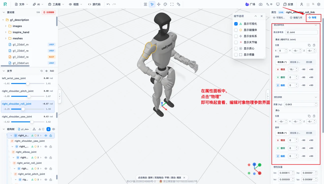
Link Physical Parameters
| Parameter | Meaning |
|---|---|
| Mass | Part mass; must be positive |
| Center of Mass | Mass center position, affects robot balance |
| Inertia | Rotational inertia around each axis, affects rotational stability |
Mass, center of mass and inertia should come from real design data or CAD data. For symmetric left and right parts, check whether parameters match.
Joint Physical Parameters
| Parameter | Meaning |
|---|---|
| Damping | Joint damping coefficient, simulates joint resistance |
| Friction | Joint friction coefficient, affects startup torque |
Operation: select a Link or Joint -> open physical properties -> edit based on reliable data -> display center of mass and inertia to check results -> export and verify in the target simulation environment.
Hardware Parameter Editing
Hardware parameters are platform extensions used to record robot actuator and transmission information. These parameters are not standard URDF fields and are usually included in CSV or BOM exports.
Operation: select the corresponding joint or part -> find the hardware properties area in the right properties panel -> fill in motor model and transmission parameters.
| Parameter | Meaning |
|---|---|
| Motor model | Select or specify the motor |
| Gear ratio | Reducer transmission ratio |
| Damping | Joint damping coefficient |
| Friction | Joint friction coefficient |
Hardware parameters should come from robot manuals or design files. If a value cannot be confirmed, leave it blank instead of guessing.
Part and Joint Operations
Create Link
Operation: click the "+" button at the top of the structure tree -> choose "Add Link" -> set the name -> add visual geometry (mesh and pose) -> add collision body -> fill in physical parameters -> create a Joint to connect it to the robot.
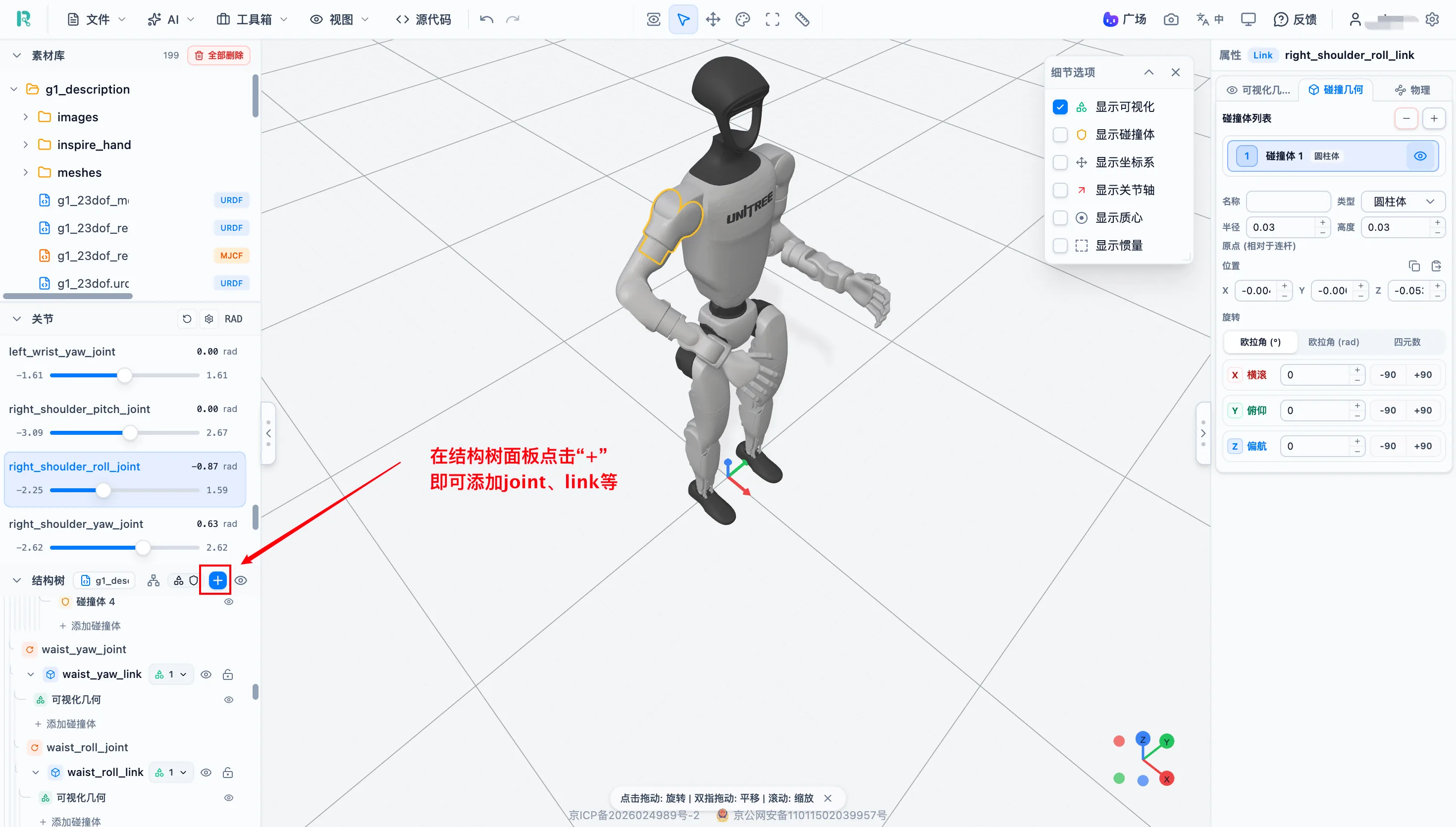
When creating a Link:
- The Link name must not duplicate an existing object.
- A new Link must be connected to the robot through a Joint.
- A part that has only appearance but no collision body or physical parameters cannot support complete physics simulation.
Create Joint
Operation: click the "+" button at the top of the structure tree -> choose "Add Joint" -> set the name -> choose parent Link and child Link -> set joint type -> set joint origin, joint axis and motion range -> preview motion in the joint panel.
When creating a Joint:
- Fixed-mounted components usually use Fixed joints.
- Rotating joints should have reasonable motion ranges.
- Preview the full motion process after creation.
Deletion Notes
Operation: select an object in the structure tree -> right-click it, or double-click in the control panel -> click Delete -> confirm whether child parts are included.
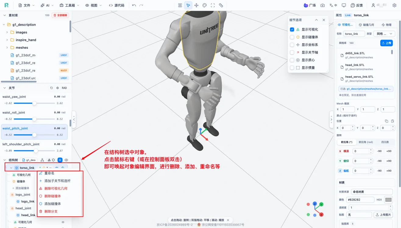
Deleting a Link also affects its child Links, Joints, visual models and collision bodies. Export a project backup before major deletion operations.
AI Review
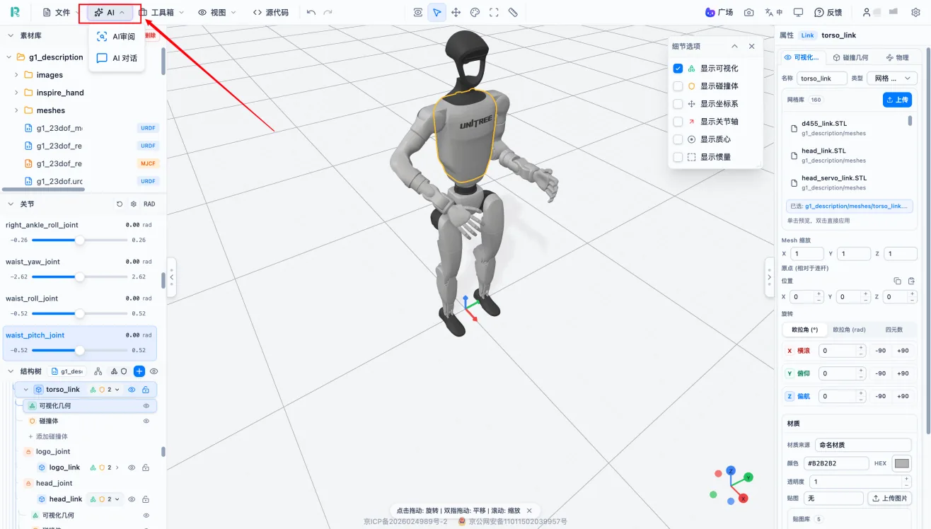
Operation: click "AI" in the top toolbar -> enter AI Review -> choose a model -> start review -> read issues and suggestions -> confirm manually before editing.
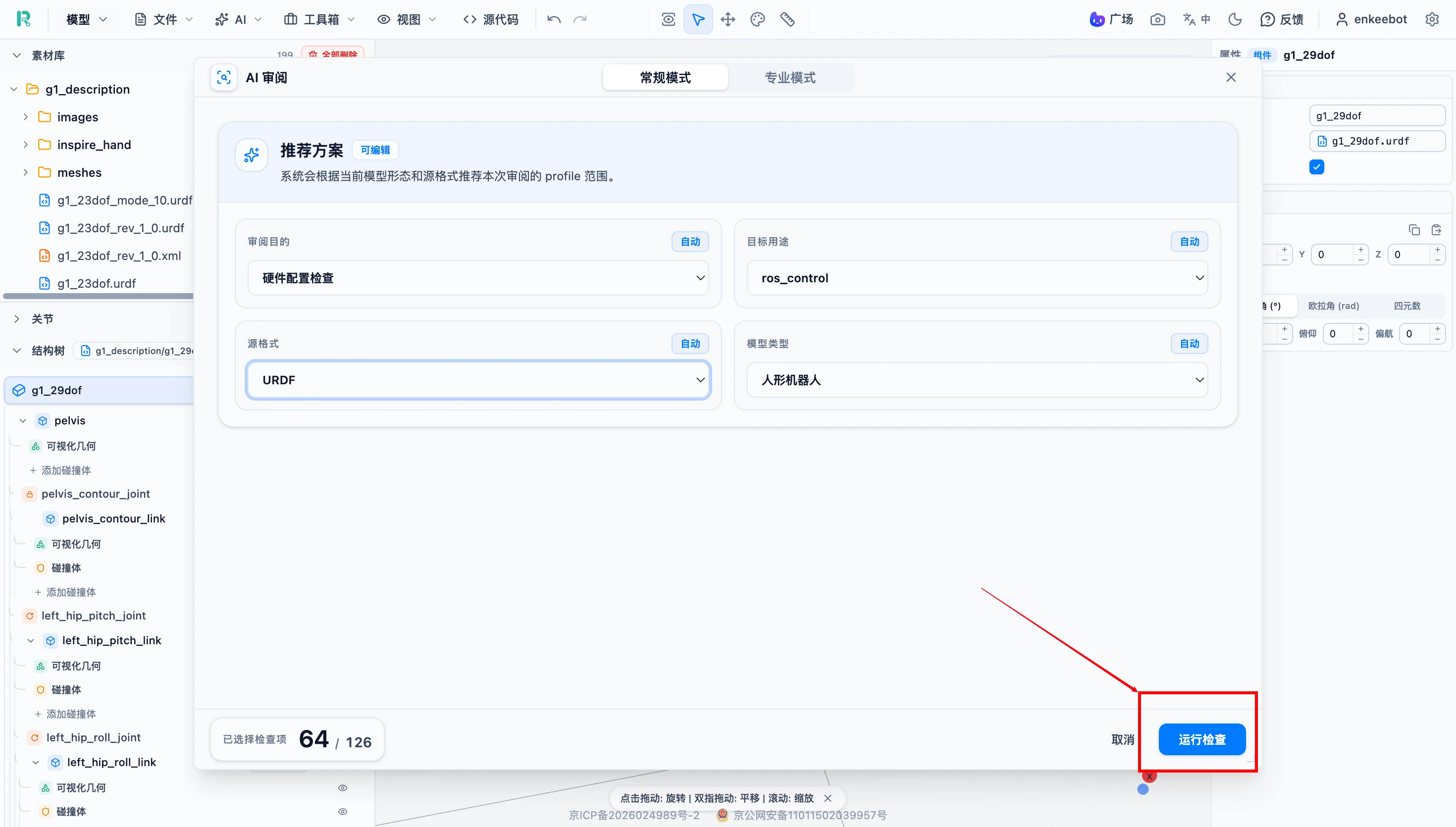
After entering AI Review, the default mode is regular mode. Choose the intended use, format and type as needed, then click "Run check".
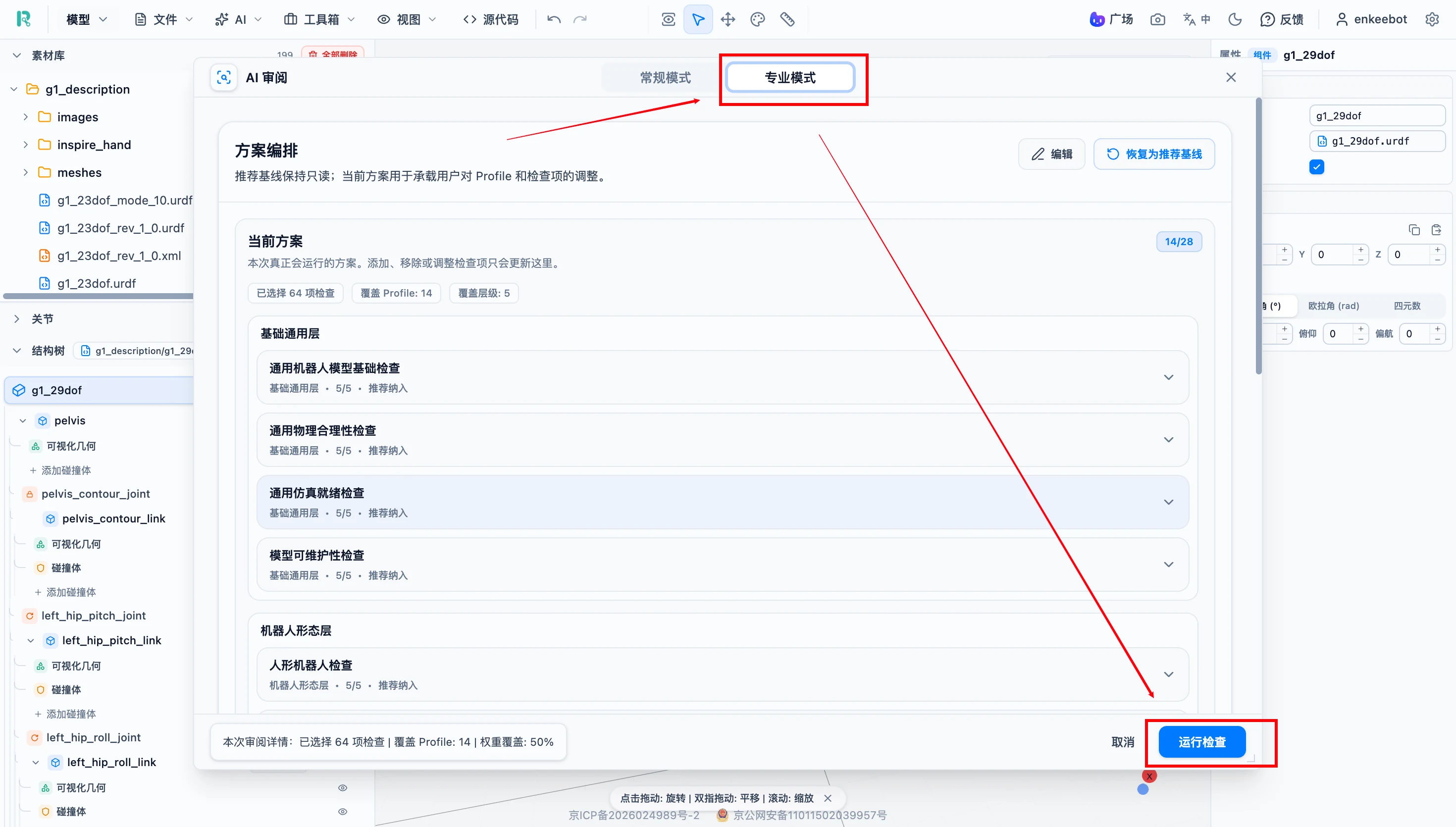
For a more comprehensive check, switch to professional mode, configure more detailed rules, then run the review.
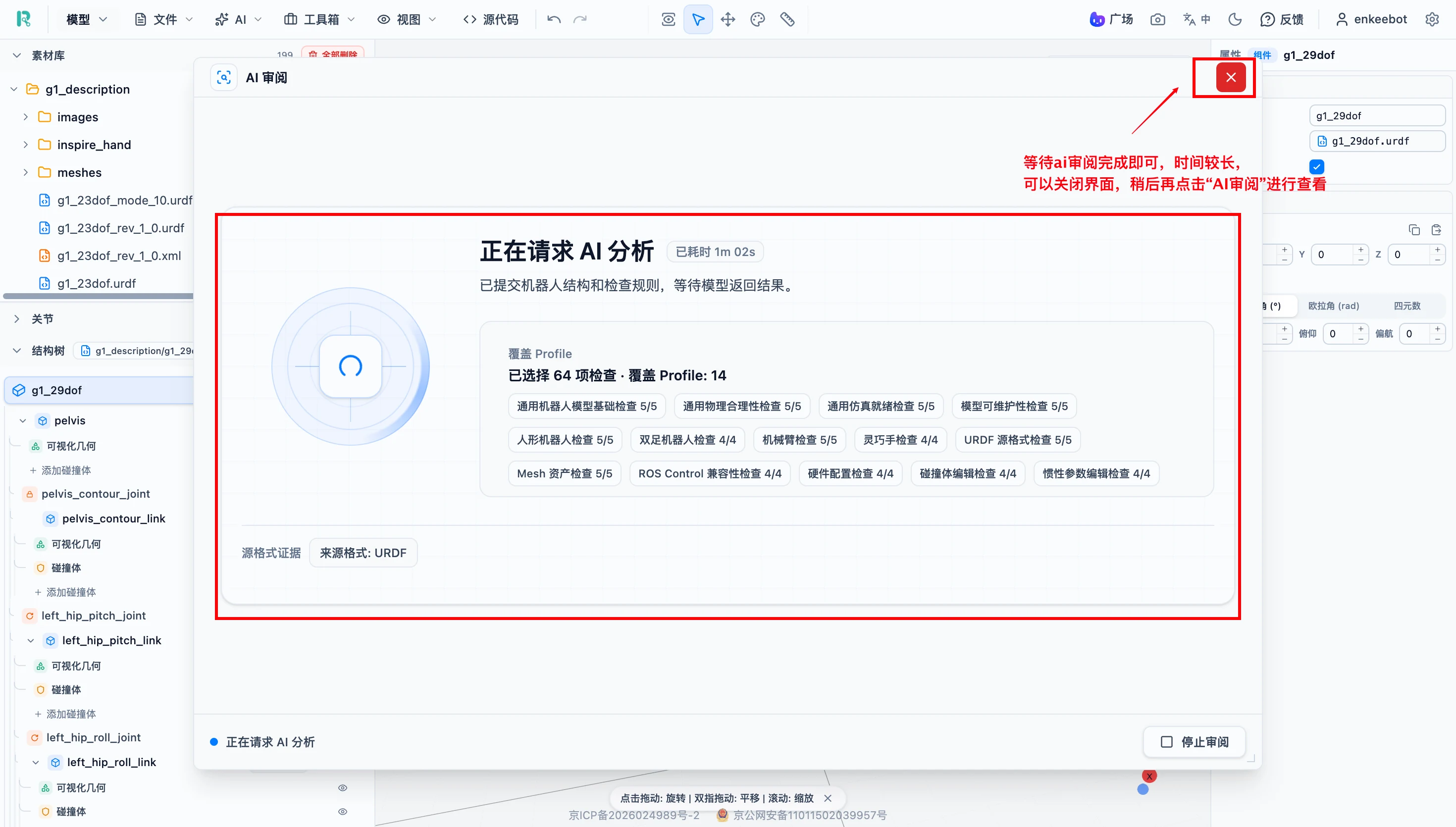
After running the check, the page shows review progress. The review may take some time, so you can close the window and continue other work, then return later.
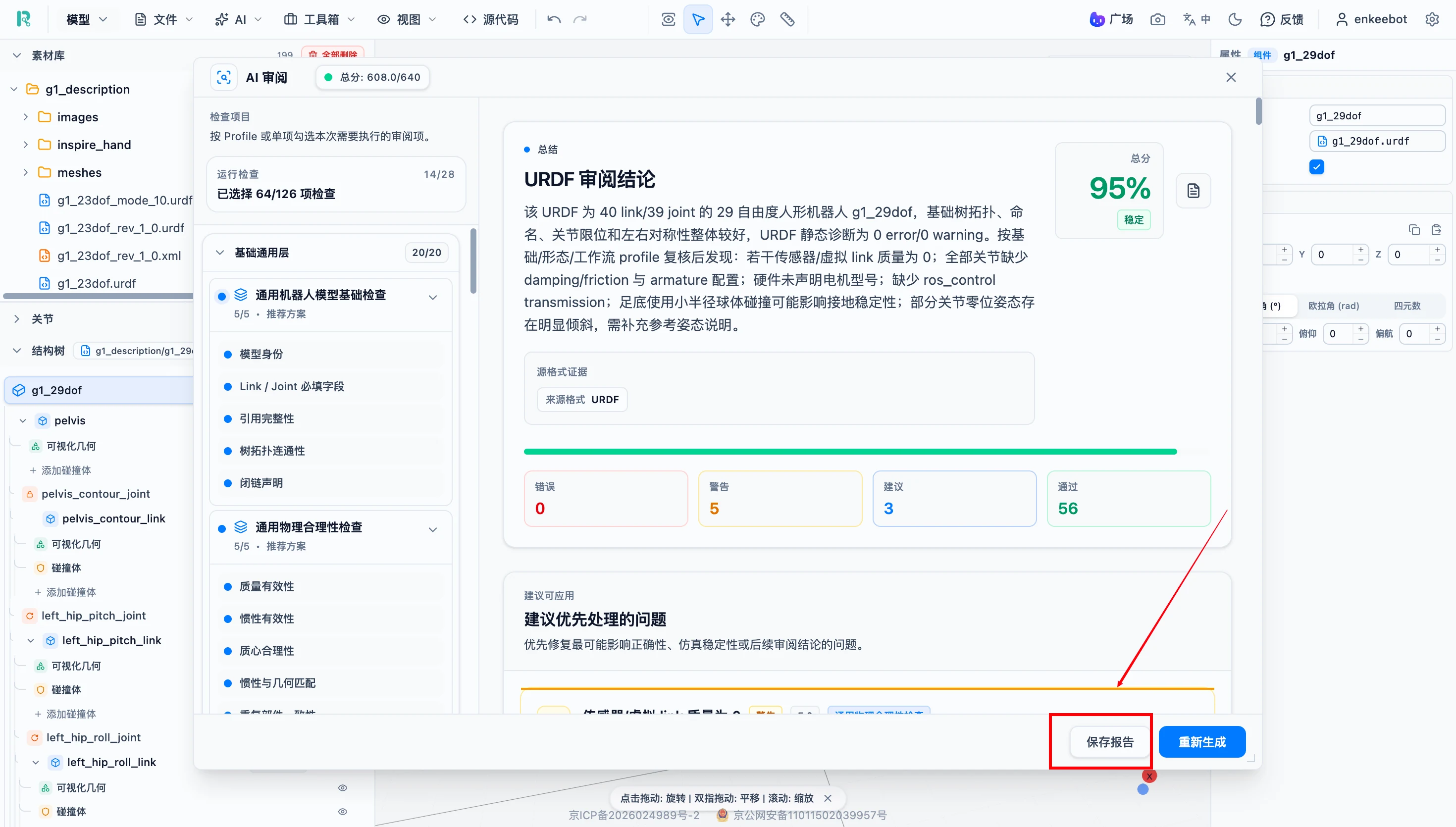
When AI Review finishes, it shows a report that can be downloaded and viewed.
AI Review is an auxiliary tool and does not replace manual inspection or simulation validation. Real hardware parameters such as mass, inertia and motor data should still come from reliable sources. Joint motion limits and collision bodies still require manual confirmation for the actual simulation task.
Auxiliary Tools
Measurement Tool
Operation: click the measurement tool in the top toolbar -> select two measurement points in the 3D view -> read the result -> exit measurement mode when finished.
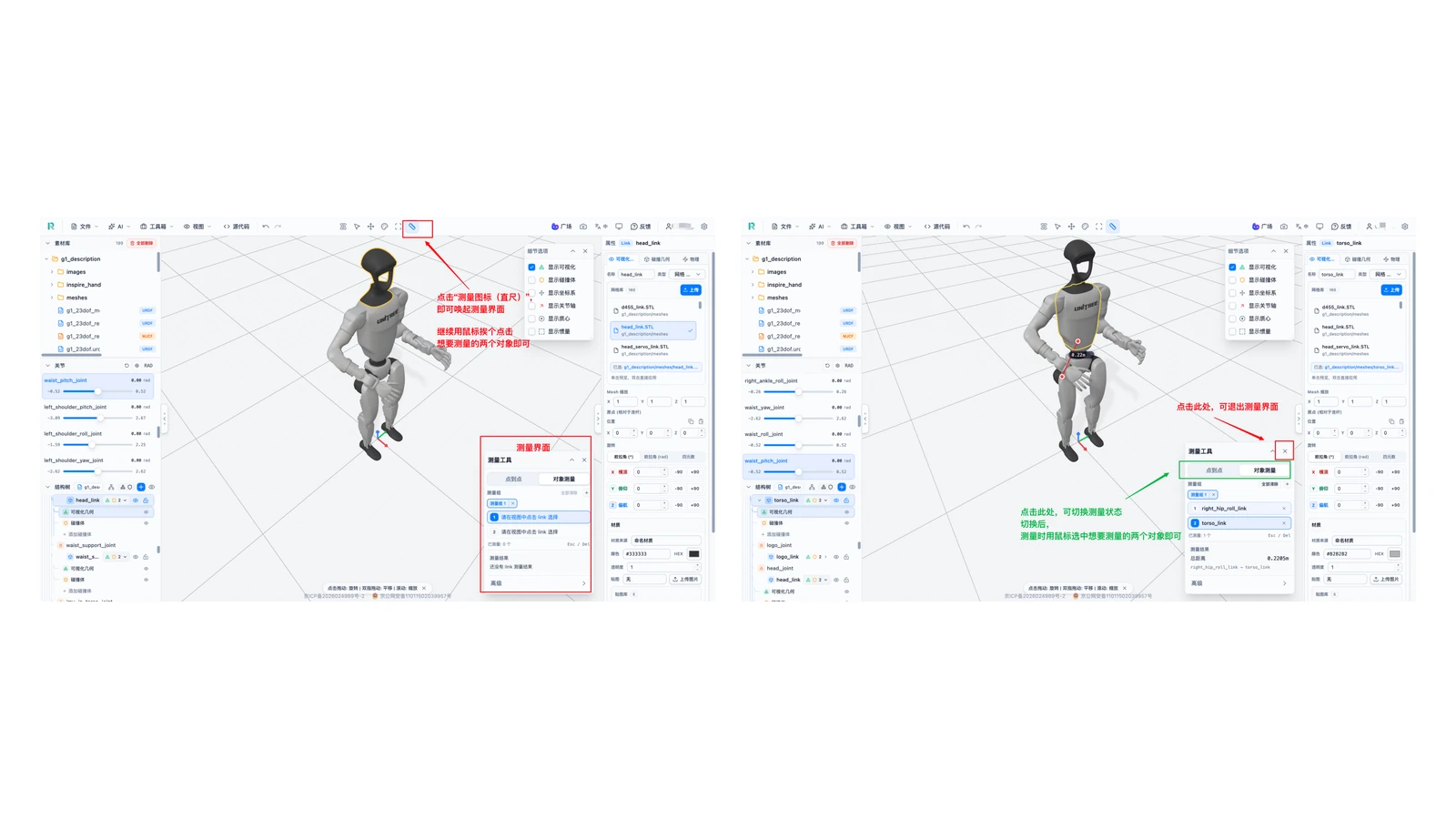
Use it to measure robot height, arm span, sensor mounting distance and similar dimensions.
Note: Confirm model scale before measuring, otherwise the result is not useful.
Source Code
Operation: click "Source code" in the top toolbar to download, copy or save source code.
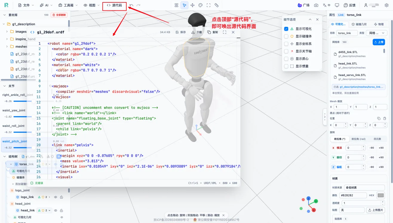
Undo and Redo
The top toolbar provides Undo and Redo for reverting the previous action or restoring an undone action.
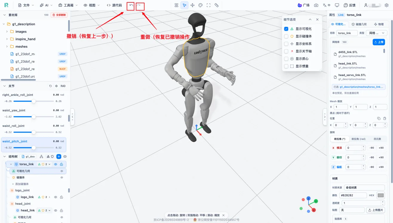
Note: Undo and Redo do not replace file backups. Export after important stages.
Model Snapshot
Operation: adjust the camera view -> set the display content -> click the snapshot feature in the top toolbar -> save the image locally.
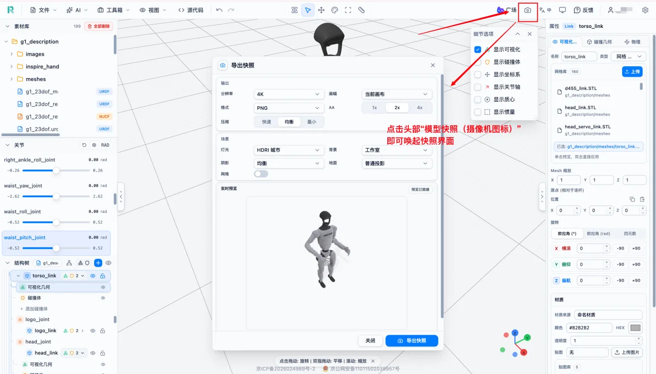
Use snapshots to create resource covers, record before/after states or prepare project report images.
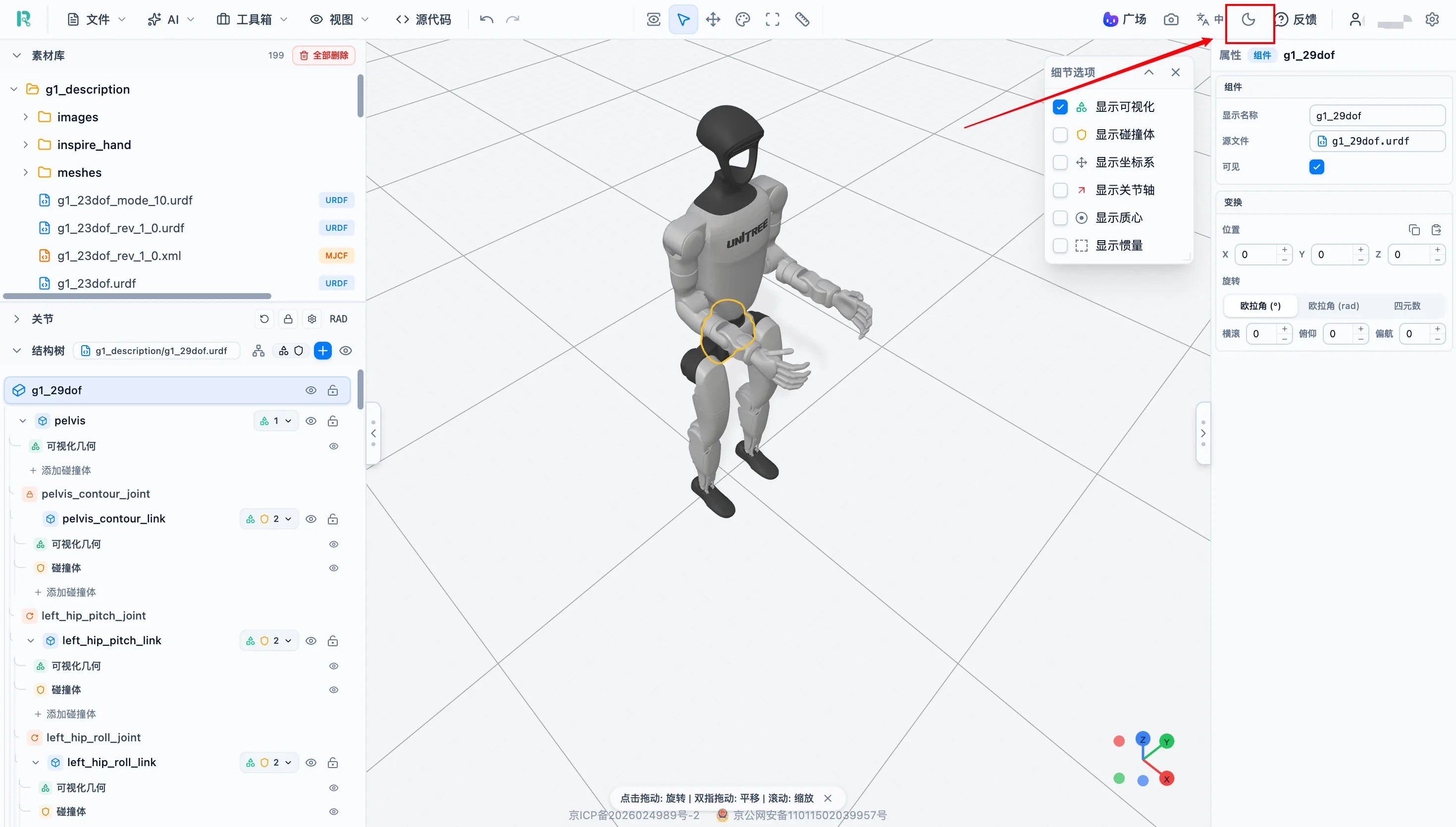
Dark Mode Toggle
Operation: click the dark-mode icon in the top toolbar to switch between dark mode and light mode.
Combine Robots and Components
URDF Studio supports importing multiple robots or components into the same workspace and creating connection relationships. Typical scenarios include mounting a gripper on a robotic arm, mounting an arm on a mobile base, adding sensors or combining multiple components.
What Is a Bridge Joint
A bridge joint is a Joint that connects two independent models. A normal Joint connects parent and child Links inside a single model, while a bridge joint spans two independently imported models and welds or articulates them together.
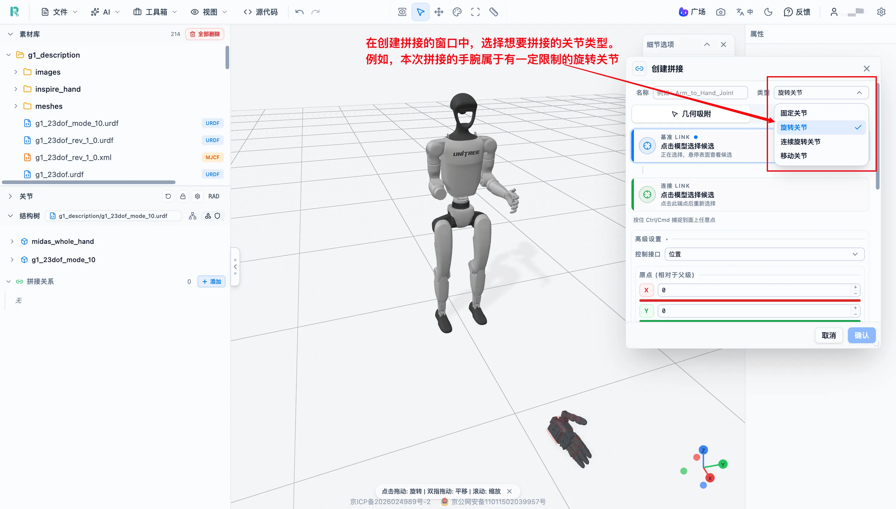
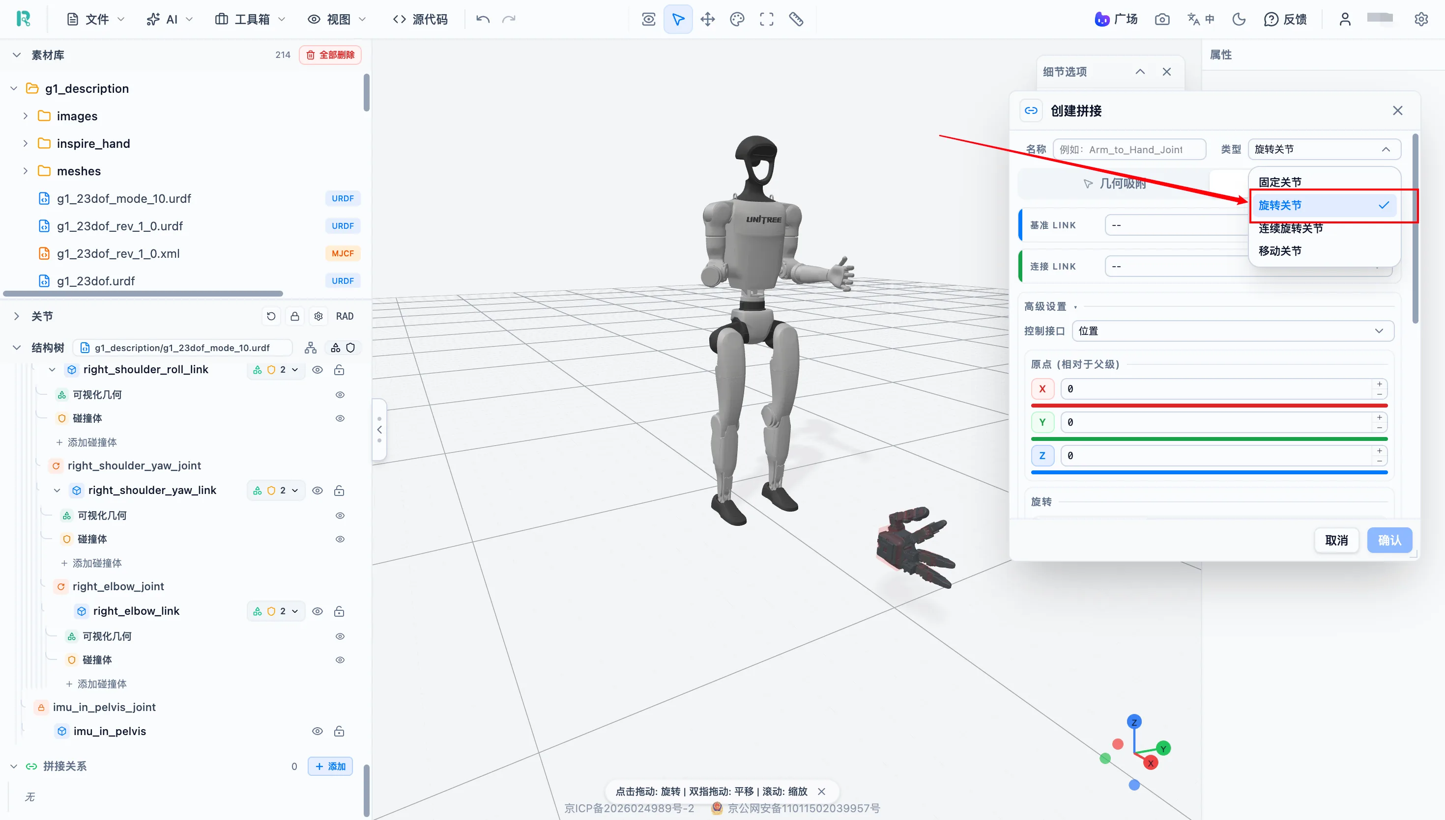
Bridge joint types follow the same choices as normal Joint types:
- Fixed-mounted sensors usually use Fixed bridge joints.
- Rotating connections, such as an arm mounted on a turntable, can use Revolute bridge joints.
Operation Steps
The following example installs a dexterous hand on a Unitree robot.
- Import the robot body model and the dexterous hand model.
- In the structure tree panel, find the bridge relationship area and click "Add". If the tree is long, scroll to the bottom or collapse nodes first.
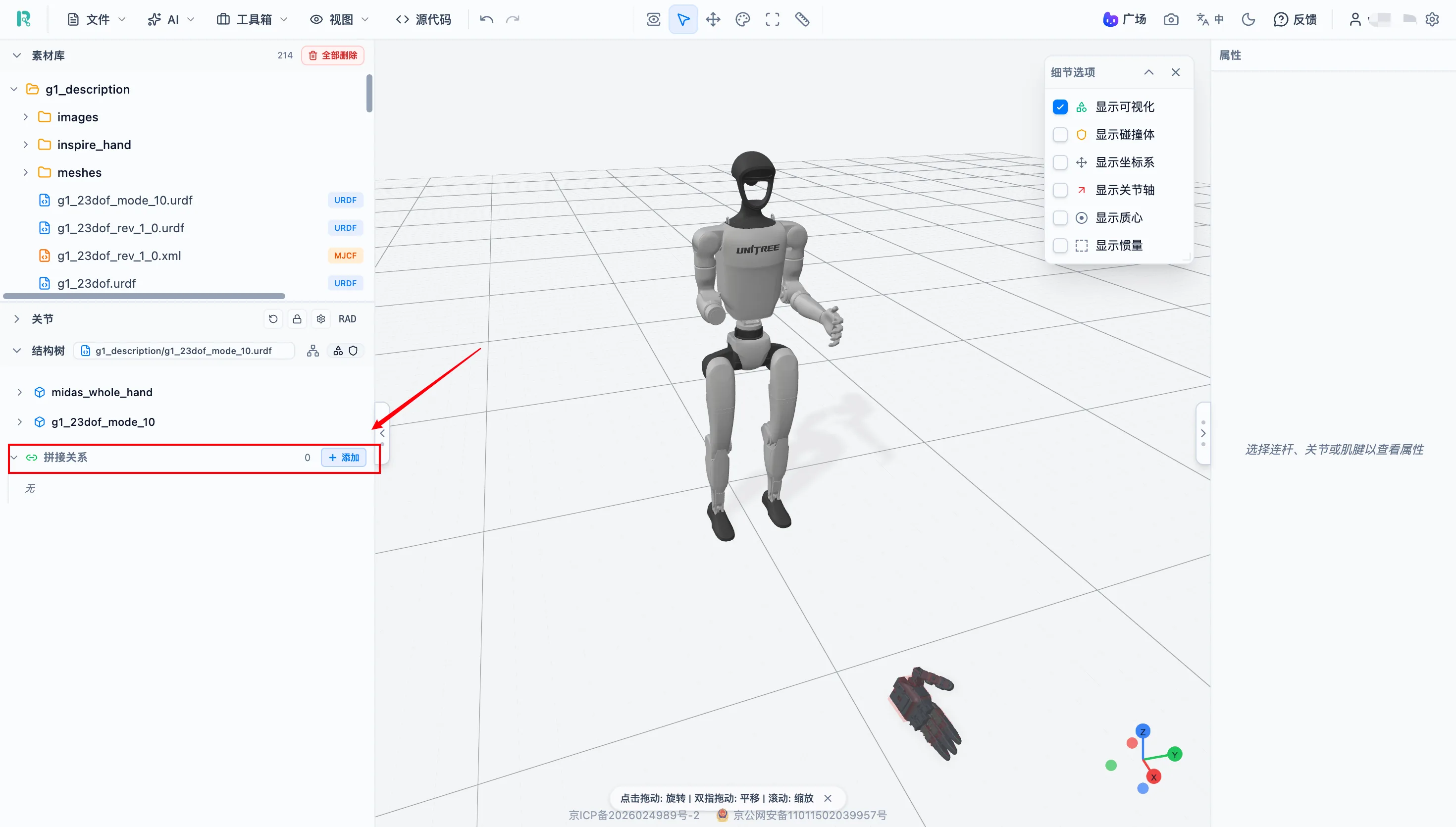
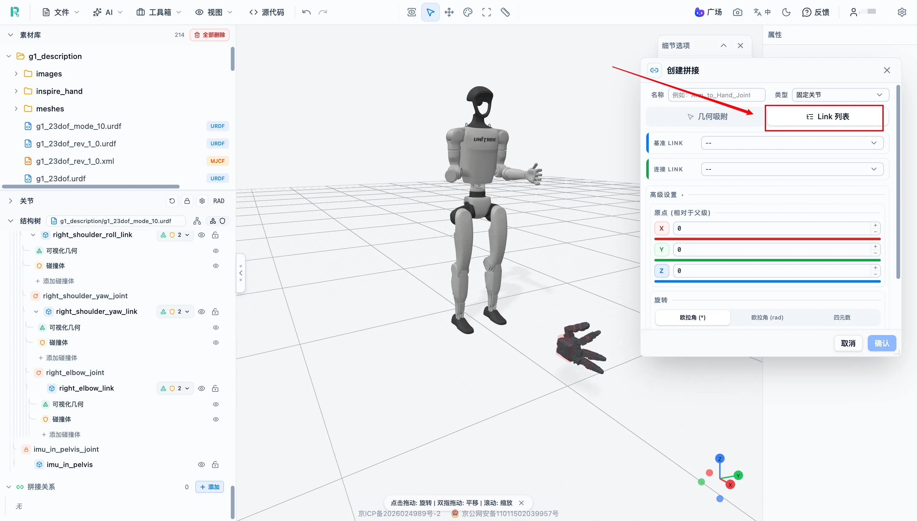
There are two joint connection methods: geometric snapping and Link splicing.
Method 1: Geometric Snapping
In the bridge creation window, choose the joint type. To make later management easier, you can also name the bridge relationship.
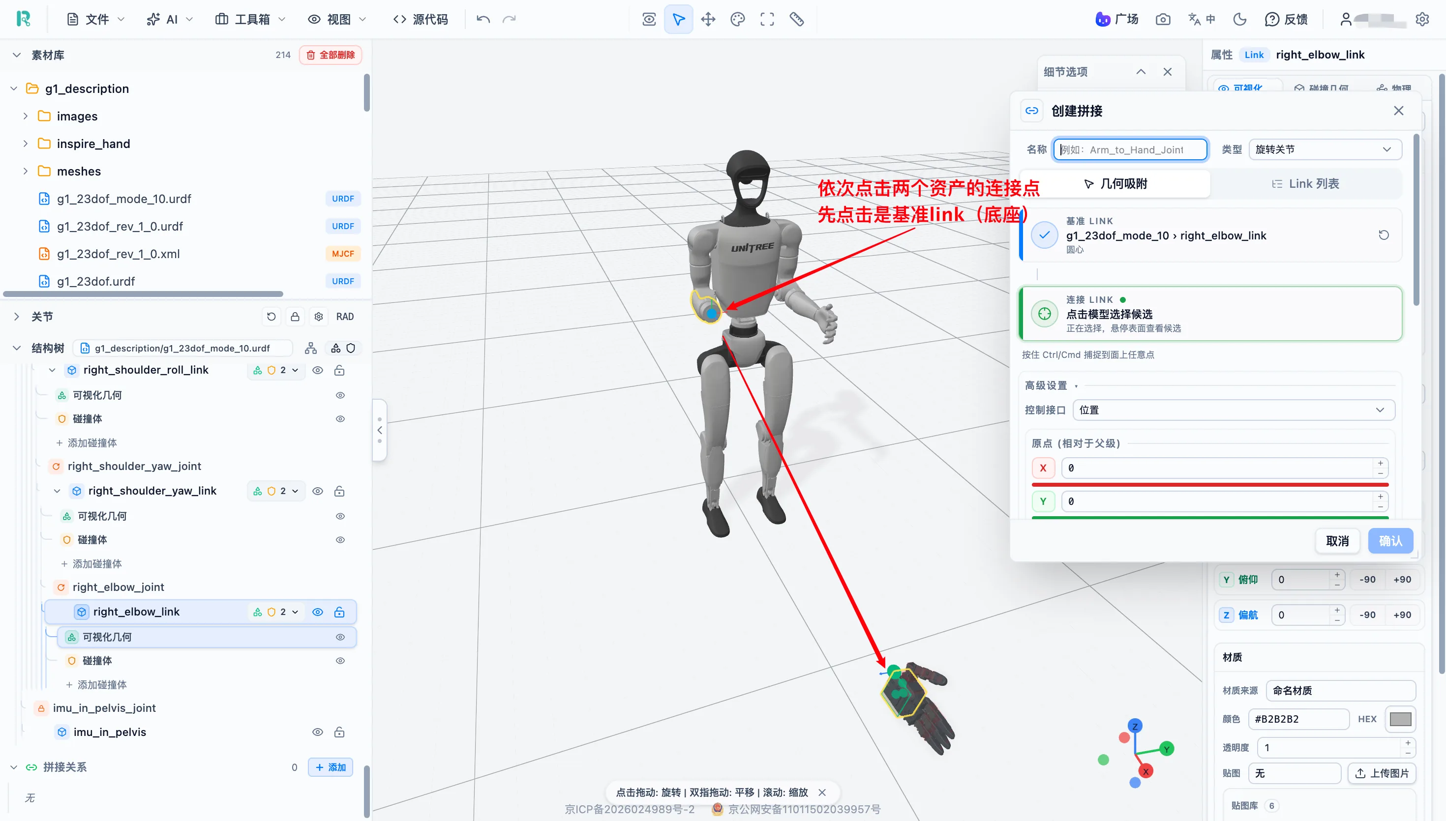
Click the joint connection points on the two assets in sequence.
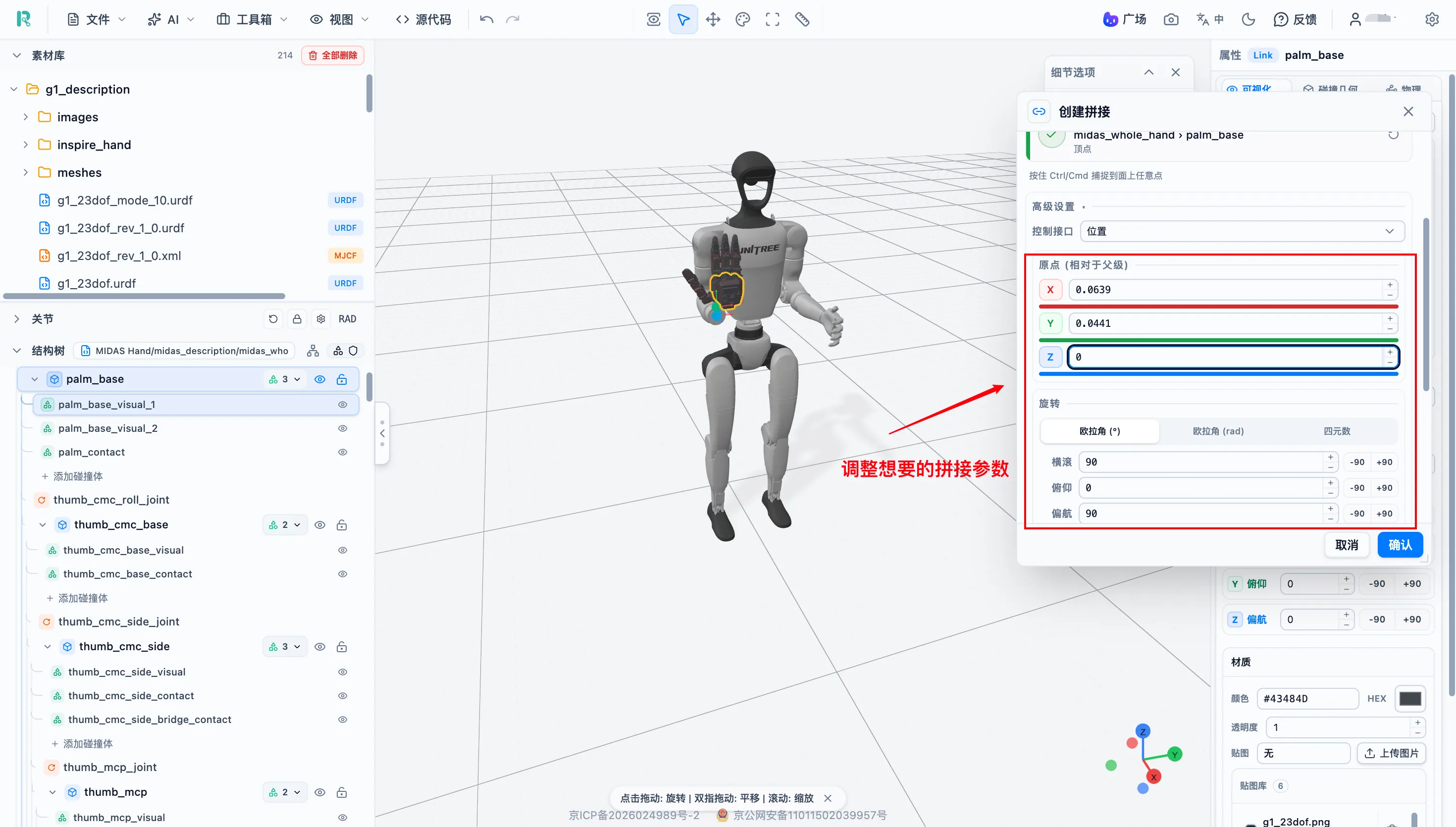
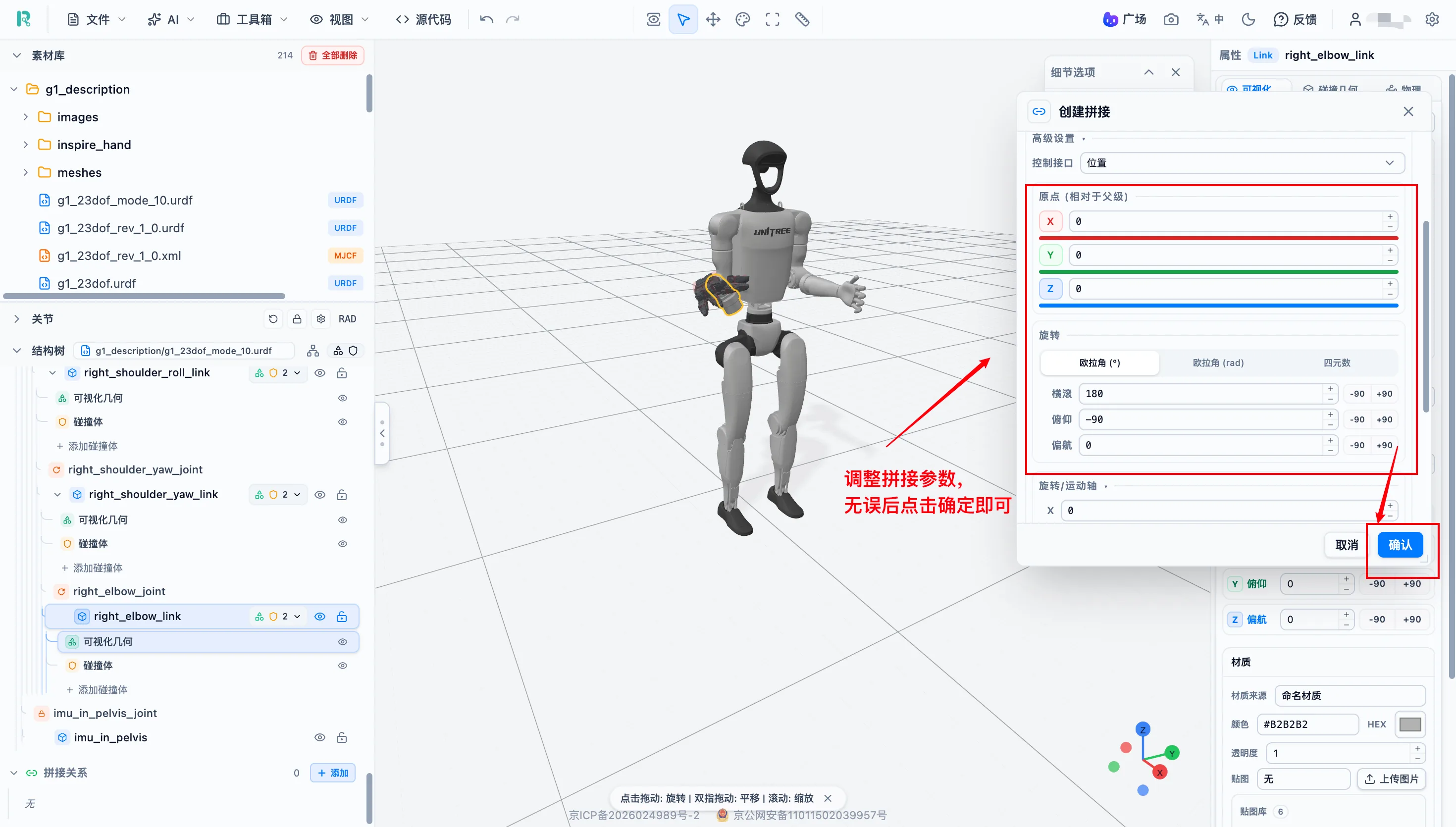
After both points are selected, the joint is connected automatically. If the pose is not ideal, adjust the bridge parameters.
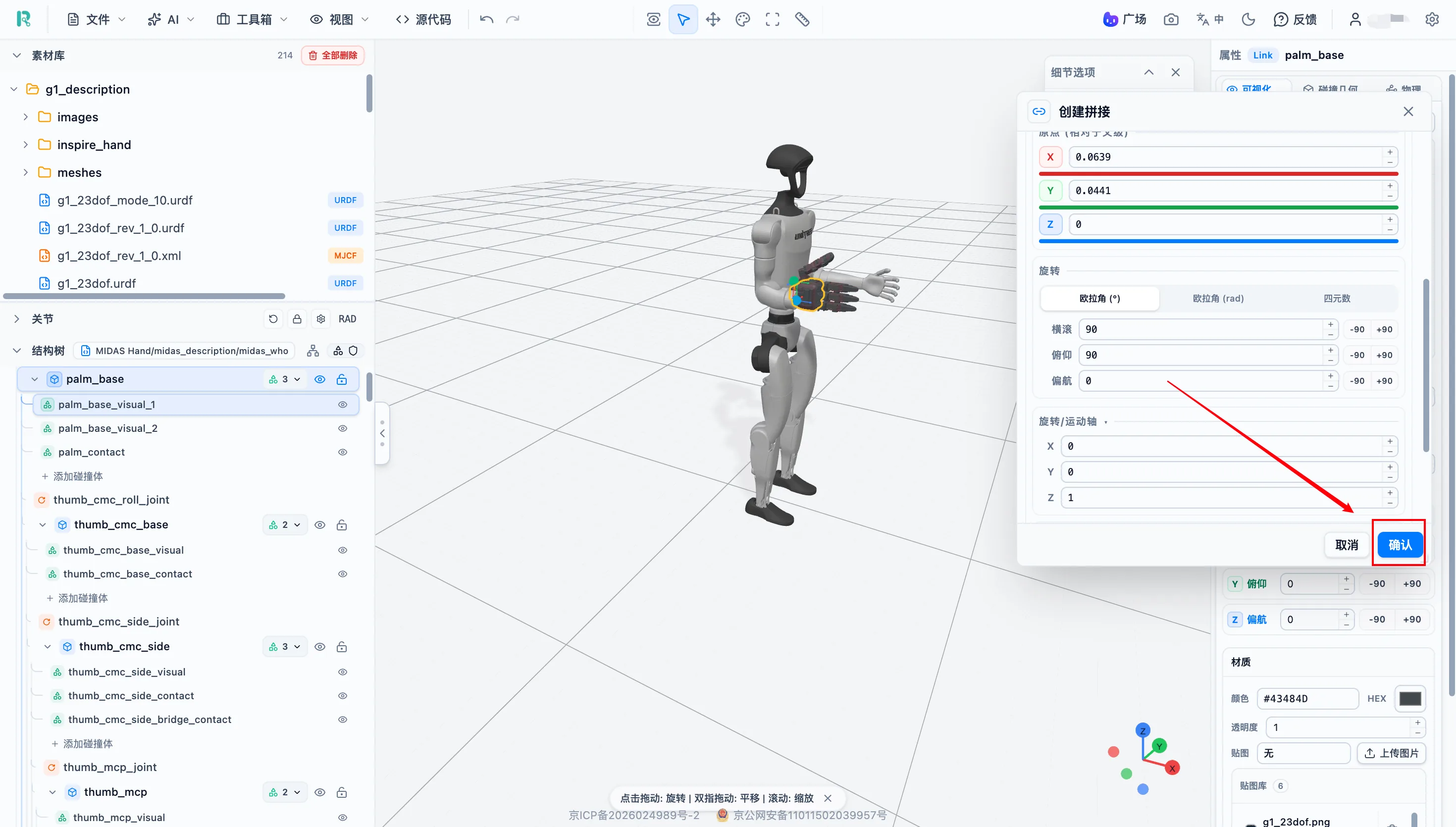
After adjustment, click "Confirm" to save.
Method 2: Link Splicing
In the bridge creation window, choose the "Link list" tab.
Choose the joint type and fill in a bridge relationship name if needed.
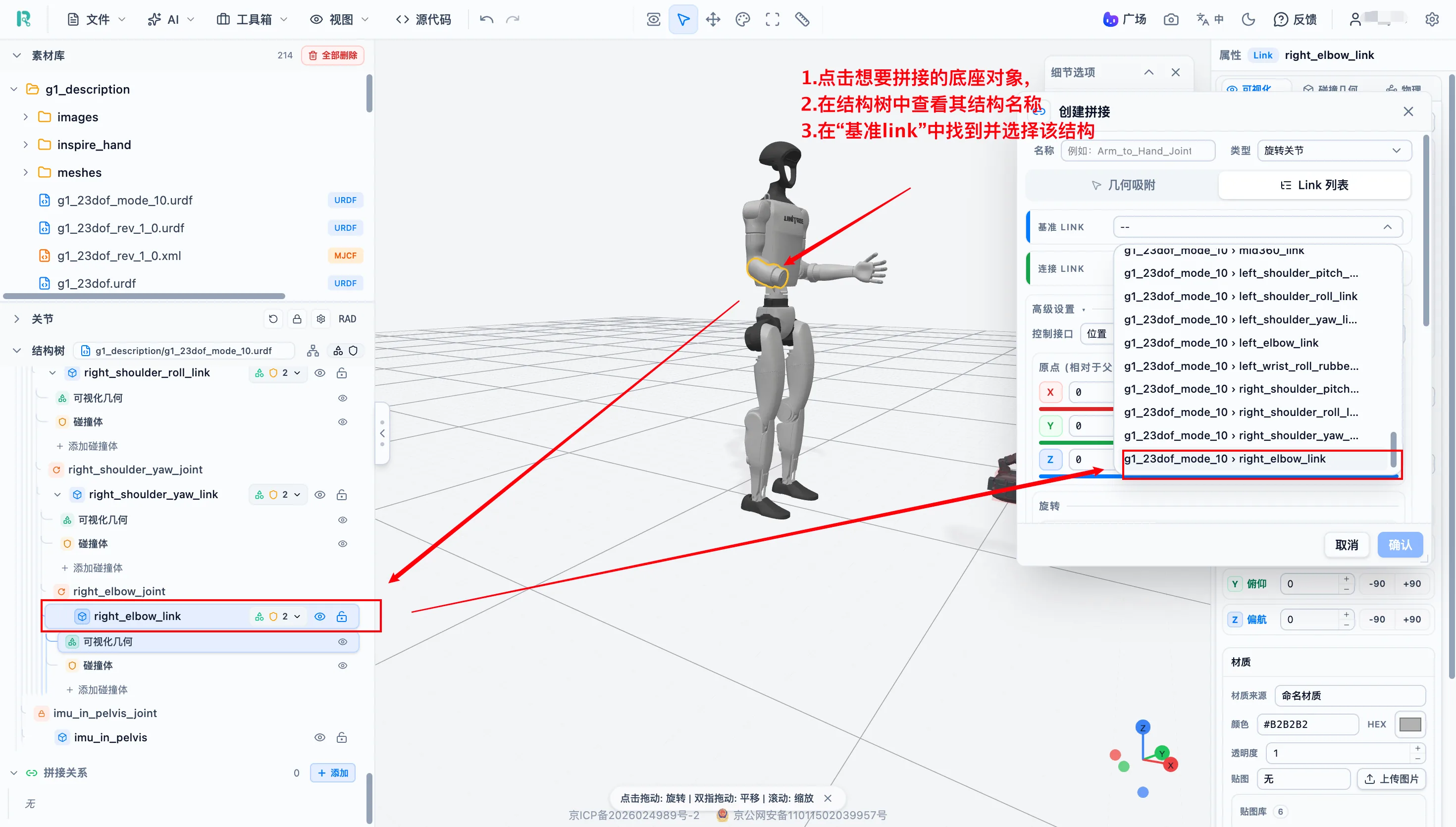
Choose the base Link. If you do not know the Link name, select the object first and then check it in the structure tree.
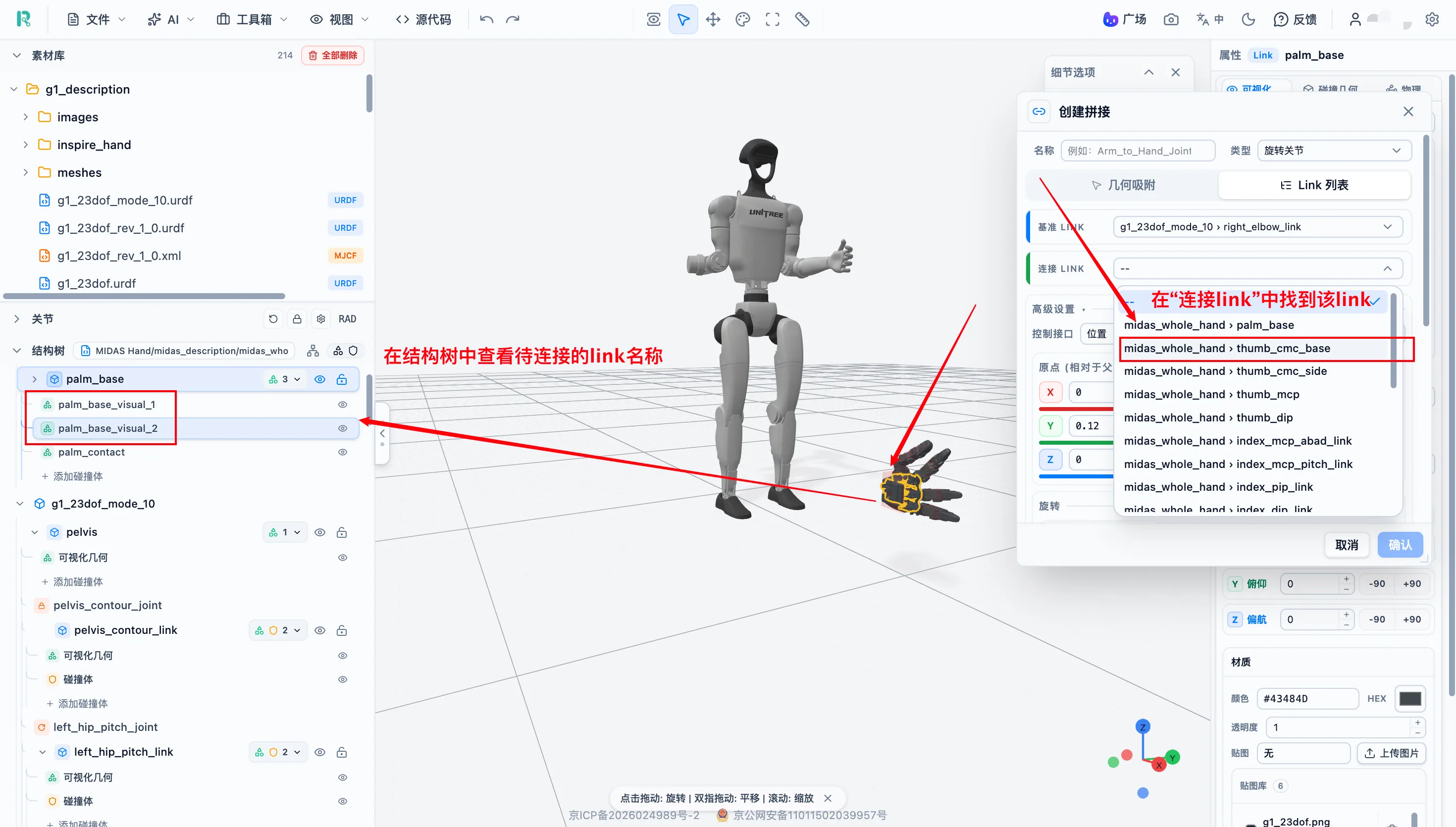
Choose the child Link. As with the base Link, you can select an object in the 3D view and confirm its name in the structure tree.
Adjust bridge relationship parameters until the pose is correct, then click "Confirm" to save.
Validate the Assembly
After splicing, check the assembled state.
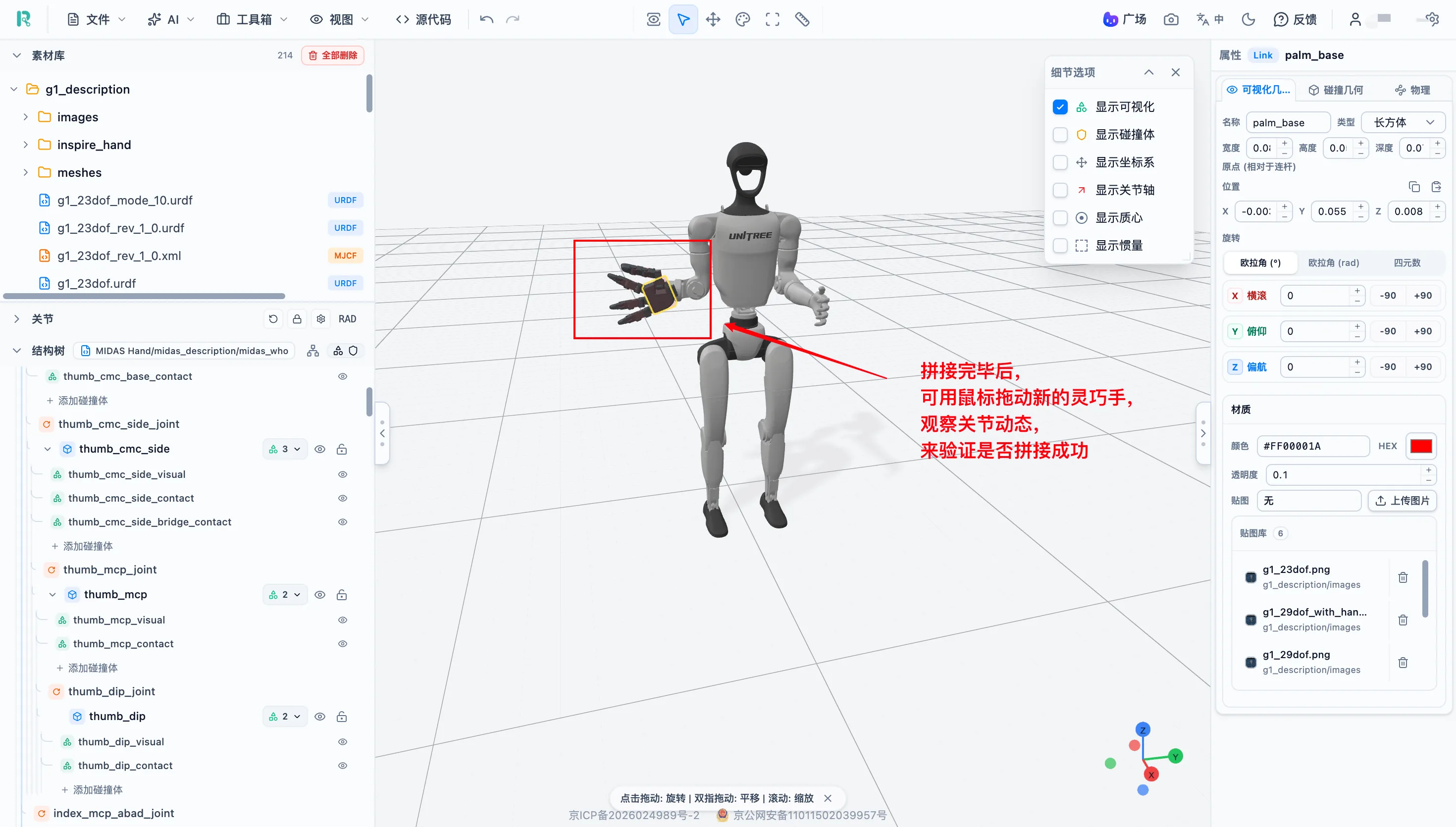
Recommended validation:
| Check | Operation |
|---|---|
| Structural integrity | Expand the structure tree and confirm that the bridge joint correctly connects the two models |
| Motion test | Drag sliders for the main robot joints and check whether the component follows correctly |
| Collision body check | Show collision bodies and confirm the mounting area has no abnormal penetration |
| Name check | Confirm that the two models do not contain duplicate Link or Joint names |
| Physical parameters | Recheck overall mass and center-of-mass distribution |
After validation passes, export the complete assembled model.
Recommendations:
- Link and Joint names should not repeat across different models.
- Fixed-mounted sensors usually use Fixed joints.
- After installing a component, recheck overall mass and center of mass.
- Export should include all referenced resources.
Export and Delivery
Supported Export Formats
| Export format | Target use |
|---|---|
| URDF | ROS / ROS 2 projects |
| MJCF | MuJoCo physics simulation |
| USD | NVIDIA Isaac Sim and 3D scenes |
| SDF | Gazebo / Ignition simulation |
| Xacro | ROS projects that need parameterized configuration |
| CSV / BOM | Parts list and joint parameter summary |
| ZIP package | Save the model and all referenced resources |
| Project file | Preserve full editing state and resume progress |
Format quick reference:
| Later use | Recommended format |
|---|---|
| Use in ROS / ROS 2 | URDF or Xacro |
| Simulate in MuJoCo | MJCF |
| Simulate in Gazebo | SDF |
| Use in Isaac Sim | USD |
| Save and transfer complete resources | ZIP package |
| Save progress for later editing | Project file |
Export Operation
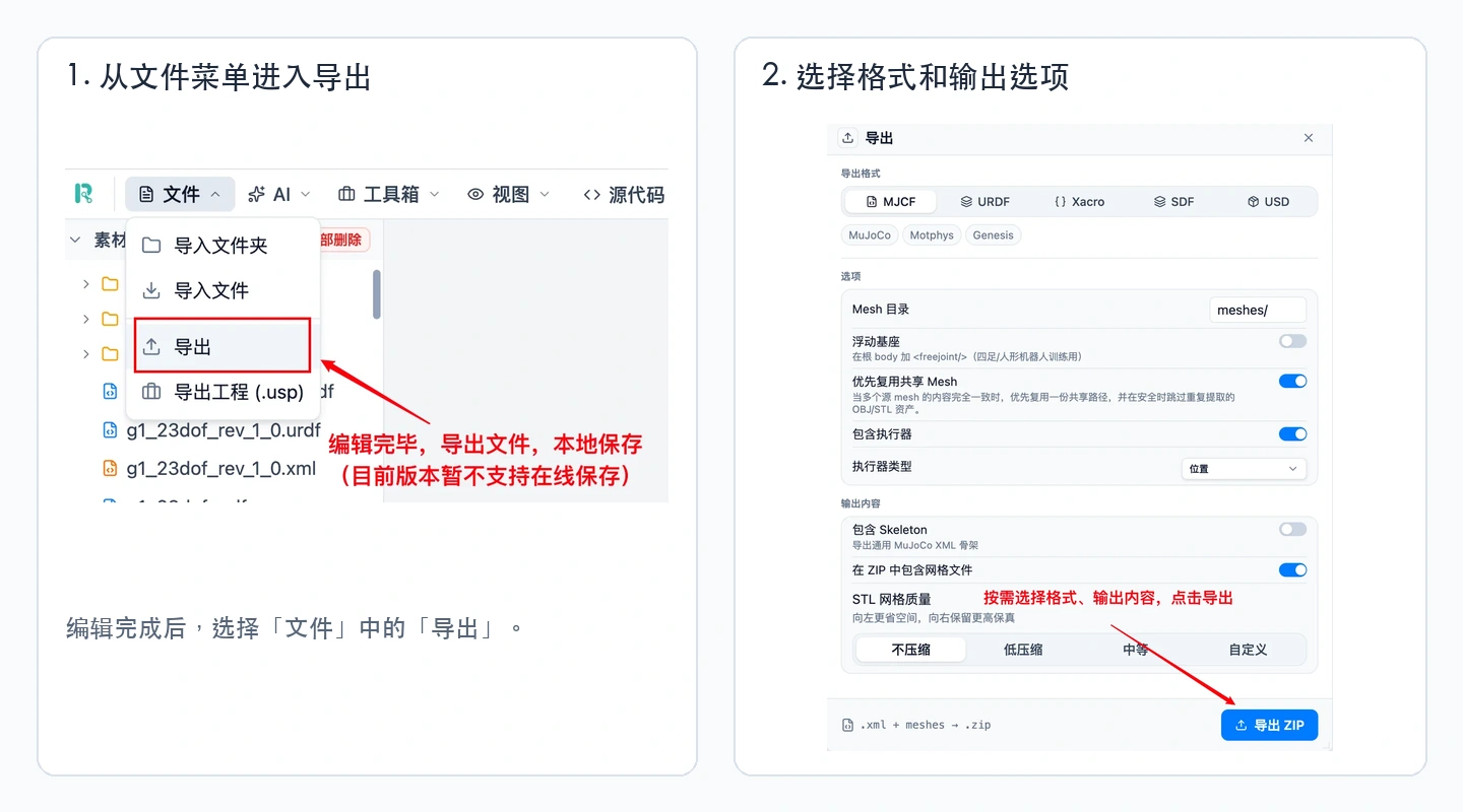
Operation: top "File" -> "Export" -> choose format -> wait for export -> choose a save location.
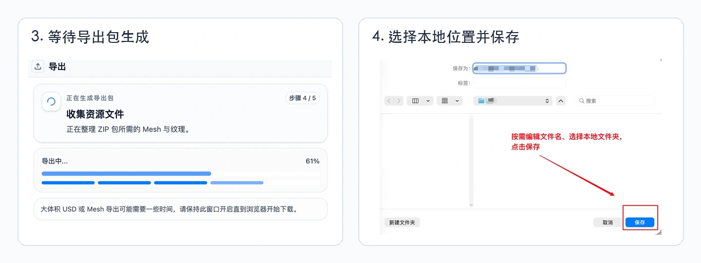
After the export package is generated, choose a local save location and click "Save" to complete export.
Before export, check: complete structure -> normal joint motion -> no missing meshes or textures -> reasonable collision bodies -> no duplicate names -> complete referenced resources.
Note: The current version does not support online saving. After export, check whether the expected files were generated in the local folder.
Connections With Other Products
BotWorld (get model) -> URDF Studio (inspect/edit/assemble) -> Export -> Simulation or publishing.
| Direction | Description |
|---|---|
| BotWorld -> URDF Studio | Import robot models directly without manual download and upload |
| URDF Studio -> BotWorld | Export edited work and publish it to BotWorld for other developers |
FAQ
| # | Problem | Common cause | Solution |
|---|---|---|---|
| 1 | Importing from BotWorld does not open URDF Studio | Not signed in, browser blocked a new page, network error | Sign in; check browser pop-up blocking; click "Import to workspace" again; or download locally and import manually |
| 2 | Local model cannot be imported | Unsupported format, incomplete ZIP structure, damaged file, special characters in path | Check supported formats; unzip and confirm it contains the description file and meshes; keep the original folder structure |
| 3 | Model is incomplete after import | Missing meshes or textures, wrong reference paths, case mismatch | Check meshes and images in the asset library; inspect source references; import the complete folder again |
| 4 | Model scale or direction is abnormal | Unit mismatch, wrong scale parameter, coordinate-system change during conversion | Check scale parameters in the properties panel; use the measurement tool on a known dimension; inspect root part position and rotation |
| 5 | Cannot select a part or find it in the structure tree | Part is occluded, measurement mode is active, node is not expanded | Exit other tools; rotate and zoom the view; check Detail Options; expand the structure tree level by level |
| 6 | Parts separate or disconnect after structural edits | Parent Link or key Joint deleted, wrong parent-child settings, duplicate names | Undo first; check disconnected Links and Joints; create missing joints; confirm connection from the root down |
| 7 | Joint cannot move | Fixed joint, same min/max value, zero range, wrong parent-child setting | Check joint type and motion range; check parent and child Links; confirm joint axis direction |
| 8 | Joint moves in the wrong direction | Wrong joint axis, wrong joint origin rotation, parent and child Links reversed | Enable coordinate frame and joint axis; drag slider to observe; change one parameter and retest immediately |
| 9 | Parts intersect or separate during joint motion | Wrong joint origin, excessive motion range, unreasonable collision body | Restore initial position; show joint axis to confirm rotation center; drag slowly to find the abnormal angle; adjust range or collision body |
| 10 | Color changes do not appear | Selected Link instead of visual geometry, texture overrides color, multiple Visual objects | Expand the Link and select a specific visual geometry; check whether multiple Visual objects exist; inspect texture settings |
| 11 | Collision body position or size is wrong | Wrong position/rotation parameters, inconsistent scale, appearance edited without collision update | Enable collision body display; inspect from multiple views; compare again with visual model after adjustment |
| 12 | Model shakes, falls or flies apart in simulation | Collision bodies intersect initially, invalid mass/center of mass/inertia, abnormal joint parameters | Check whether collision bodies overlap or penetrate the ground; confirm mass is positive; test without control first |
| 13 | Meshes or textures are missing after export | Exported only the description file, used external absolute paths, changed directory structure after export | Export as a complete ZIP package; confirm it contains meshes; import again to verify |
| 14 | Exported model cannot be opened in another tool | Format incompatibility, resource path error, duplicate names, disconnected structure | Confirm target tool supports the format; run source-format checks; inspect names and structure; switch export format if needed |
When troubleshooting, use this order: file completeness -> model loaded correctly -> correct object selected -> reasonable parameters -> complete export content -> target software compatibility.
If you cannot solve an issue, submit feedback or leave a message in official BotWorld accounts on WeChat, Bilibili or Xiaohongshu. The official account name is "BotWorld".
Last updated: August 13, 2026.